Rev: 09.19.23 Page 13 CCD-0007153
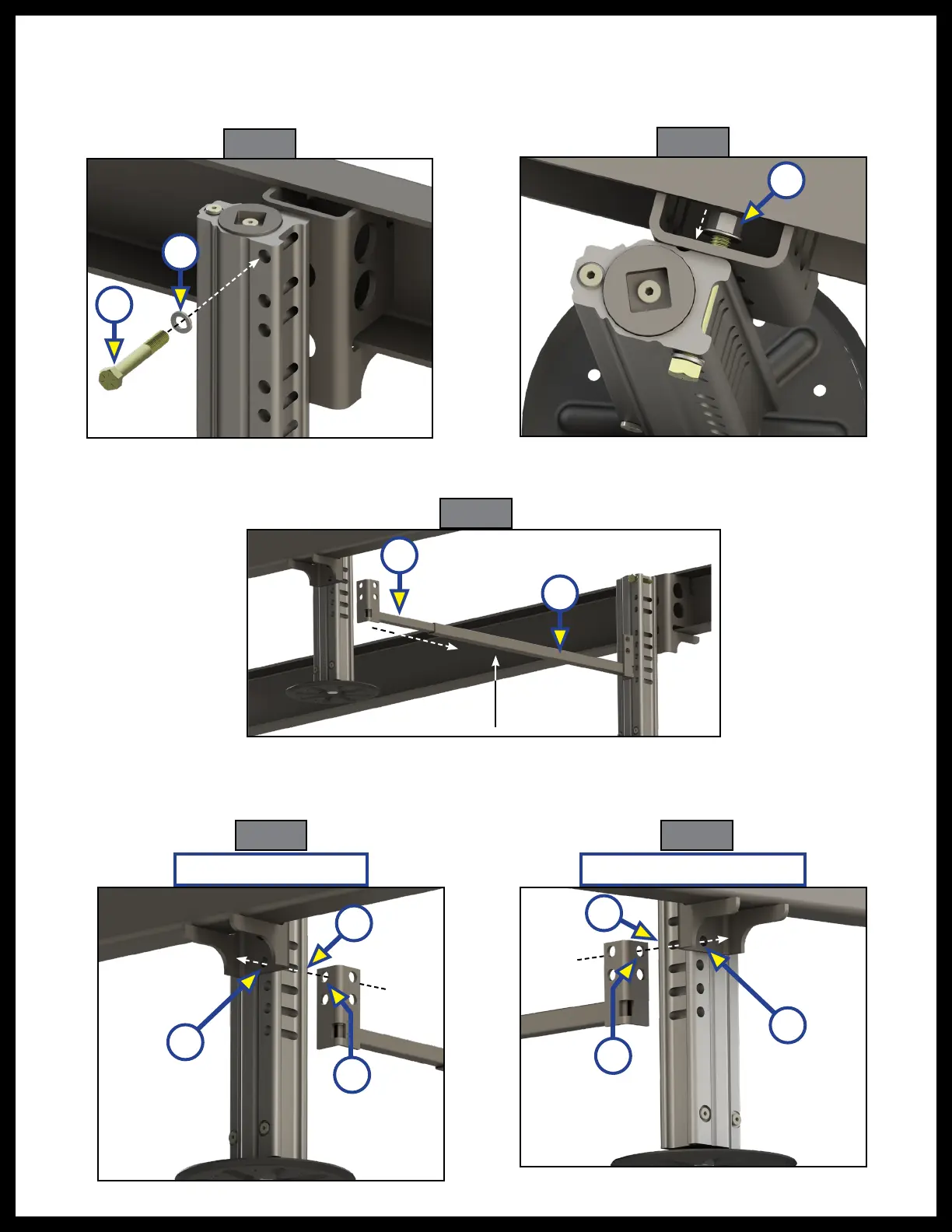
Fig. 22
Fig. 23
Fig. 24
Fig. 25
nut (Fig. 23A).
8. Repeat steps 5 and 6 with the Titan Jack on the opposite side.
NOTE: Do not torque bolts at this time as they may need to allow the jacks to swing slightly for adjustment.
9. Slide the inner crossbar beam (Fig. 24A) into the outer crossbar beam (Fig. 24B), and slide the newly
formed assembly between the two rear jacks.
10. Align fourth mounting hole from the bottom on each Titan Jack (Driver and Passenger sides,
respectively), (Fig. 25A), (Fig. 26A) with the top mounting hole of the crossbar bracket (Fig. 25B),
(Fig. 26B) and the bottom mounting hole of the jack bracket (Fig. 25C), (Fig. 26C).
11. Slide a 1/2” - 13 X 3 1/2” bolt (Fig. 27A), (Fig 28A) through a 1/2" split washer (Fig. 27B), (Fig 28B) and
Fig. 26
A
Driver Side Rear Jack
Passenger Side Rear Jack
A
B
C
A
B
A
B
C
A
B