Rev: 09.19.23 Page 14 CCD-0007153
then through each set of holes once aligned to pin the crossbar assembly in place (Fig. 27C), (Fig 28C).
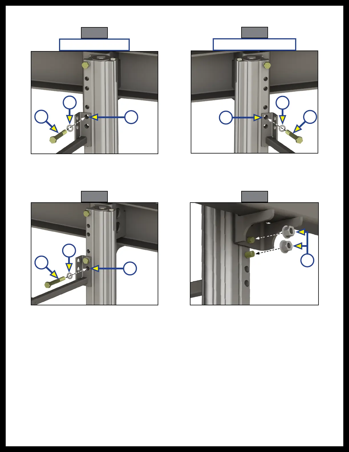
12. Move to one side of the chassis beam and insert a final 1/2” - 13 X 3 1/2” bolt (Fig. 29A) through a 1/2"
Fig. 27
Fig. 28
split washer (Fig. 29B) then through the bottom mounting hole of the crossbar bracket and Titan Jack
(Fig. 29C).
13. Secure the bottom and middle bolts with two 1/2” - 13 lock nuts (Fig. 30A).
14. Repeat steps 10-11 on with the Titan Jack, crossbar bracket, and jack mounting bracket on the
Fig. 29 Fig. 30
Driver Side Rear Jack
Passenger Side Rear Jack
A
A
C
C
opposite side of the chassis beam.
15. Torque all six nuts (one at the top, middle, and bottom of each jack) to 90 ft/lbs.
16. Secure the inner and outer crossbar components with two 2 1/4" - 14 X 1" self-drilling screws (Fig. 31A)
A
C
A
B
B
B