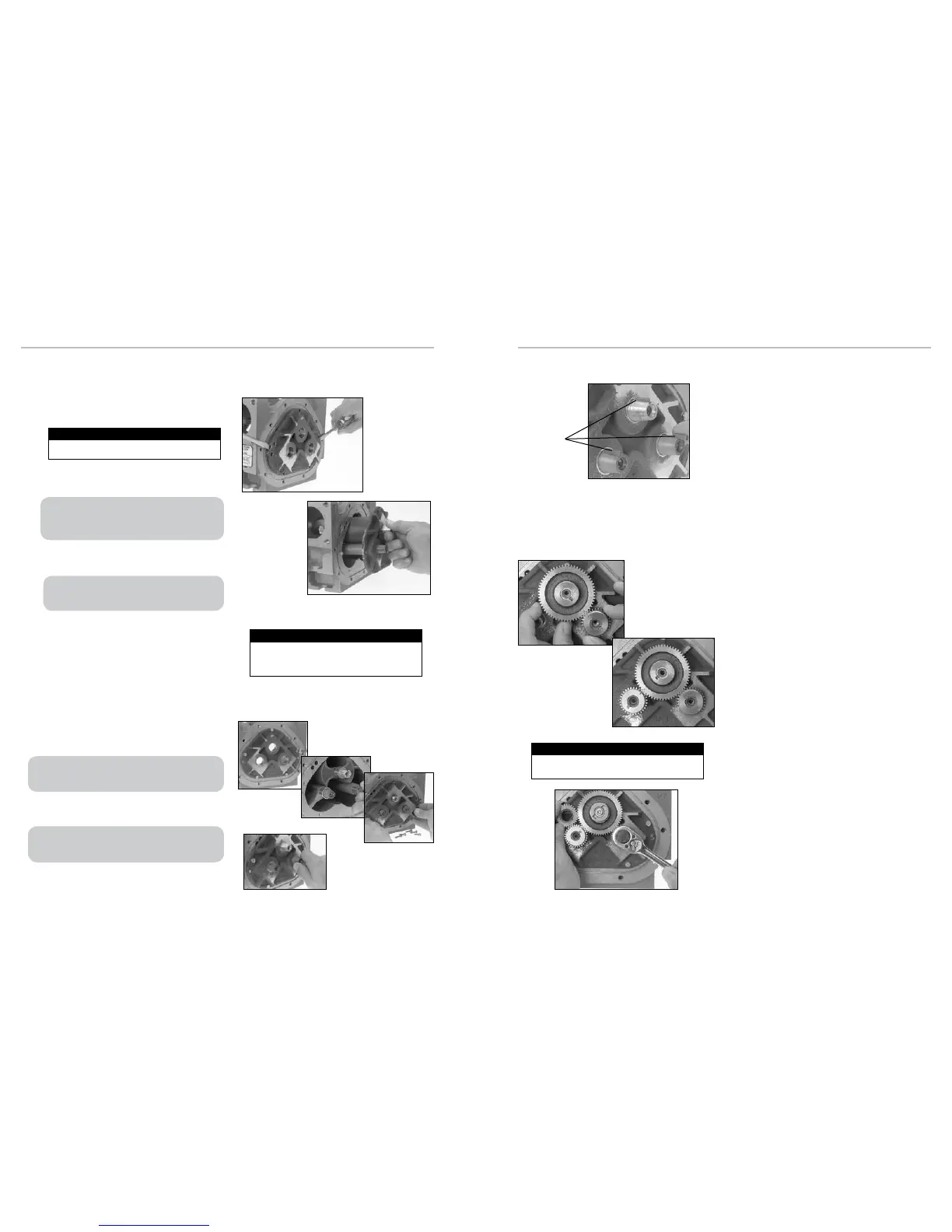
1. Insert a screwdriver into each of the two notches near
the dowel pins. Gently pry the front bearing plate off the
dowel pins.
2. Grab the end of the blocking rotor extending out from the
front bearing plate, and pull the front bearing plate and
rotor assembly straight out from the housing.
3. Remove the remaining bearing plate. Insert a screwdriver
into each of the two notches near the dowel pins. Gently
pry the front bearing plate off the dowel pins.
4. Inspect and clean all critical surfaces: gear teeth, rotors,
and internal housing faces.
• Remove any crystalline formations using ne emery cloth or
a ne wire brush.
• Remove nicks and burrs on metal parts with a stone.
• Remove all grit and other foreign particles.
• Replace all parts that appear worn or damaged.
1. Replace the non-rotor gear bearing plate to the housing
with the bearing plate screws.
2. Insert the non-tapered ends of the three rotors into the
housing and onto its respective bore of the installed
bearing plate.
3. Place the remaining bearing plate over the three tapered
rotor ends and fasten it to the housing with the bearing
plate screws.
REASSEMBLING THE METER
For MA-4, M-5, and MA-5 old style models, M-60 and
M-80 current models, pull rotor assembly with the rear
bearing plate from the housing. This will also remove the
drive reduction gear which is attached to the blocking rotor.
MA-4, M-5, and MA-5 old style models, M-60 and M-80
current models have a driven reduction gear attached by a
shoulder bolt in the center of the front bearing plate.
Be careful not to mar any of the surfaces.
Be Careful
Be careful not to mar or alter the shape of any of the
parts. Changing the shape of the parts may interfere
with their operation.
Be Careful
The rotor gears are on the rear bearing plate of MA-4, M-5,
and MA-5 old style models, M-60 and M-80 current models. On
all other models, the rotor gears are on the front bearing plate.
For MA-4, M-5, and MA-5 old style models, M-60 and M-80
current models, make sure that the teeth of the driving reduction
gear mesh with the teeth of the driven reduction gear.
Rotor Keys
continued from following page
4. The rotors should have a small amount of end-play and
be easy to turn. Test each rotor, one at a time. Turn the
rotors to make sure that they revolve freely. Jog the rotors
from end to end to check for end-play. If they do not move
easily in both tests, remove the rotors and check for
burrs and corrosion deposits. Clean them thoroughly and
repeat steps 2, 3 and 4.
5. Each rotor has a notch, or “keyway”, to hold a rotor key.
The rotor key is a small wedge of metal. Press a rotor
key into the keyway of each rotor with your thumb and
forenger.
1. Slide the blocking rotor gear over the tapered blocking
rotor end and turn it until the timing mark is in position
to line up with the timing mark on the right displacement
rotor gear. Slide the right displacement rotor gear over
the tapered end of the rotor so that the timing mark lines
up with the blocking rotor gear timing mark.
2. Turn the blocking rotor gear (turn the right displacement
rotor gear with it) until the timing mark is in position to
line up with the timing mark on the left displacement
rotor gear. Slide the left displacement rotor gear over the
tapered end of the rotor so that the timing mark lines up
with the blocking rotor gear timing mark.
3. Position the spare displacement rotor gear between
the left displacement rotor gear and the blocking rotor
gear to prevent the gears from moving. Attach the right
displacement gear washer and screw using the rotor gear
wrench.
4. Keep the spare displacement rotor gear positioned by the
left displacement rotor gear. Attach the left displacement
gear washer and screw using the rotor gear wrench.
5. Position the spare displacement rotor gear between the
right displacement rotor gear and the blocking rotor gear.
Attach the blocking rotor gear with the packing gland
driver and screw using the rotor gear wrench.
6. Rotate the gears to make sure that the rotors turn freely.
Burrs, foreign material, or marred surfaces can restrict the
rotor movements. If the rotors do not turn freely, remove
the gears and rotors and deburr and clean the surfaces
again.
TIMING THE ROTOR GEARS
Before putting the meter into service, the rotors must be timed. Rotors are timed by lining up timing marks stamped
onto the face of the gears. The timing mark on the blocking rotor gear is stamped on a gear tooth. The timing mark on
the displacement rotor gears is stamped on a space between two gear teeth. You may need to remove the gears and
reposition them several times to line up the timing marks correctly.
Tighten the gear screws to the torque specication
listed in the Torque Chart on page 22.
Torque the Gear Screw
19
18

 Loading...

