Prevent pipe strain or stress from occurring when making meter or
accessory repairs. Pipe strain and stress occurs when the pipes
are not supported or are not aligned correctly to the meter. The
weight of the pipes must always be supported independent of the
meter. This means that the meter and accessories can be easily
removed without affecting the pipes or the pipe alignment. Never
leave any of the pipes hanging.
If the meter is used for seasonal work, the meter should
be removed from the system and thoroughly ushed with a
compatible liquid at the end of each season. To ush the meter,
remove the drain plug on the front and rear covers. Then ush the
product from the front and rear covers. If ushing with water, extra
care should be taken to drain the meter completely and dry all
internal parts. Rell the meter immediately with a compatible liquid
(or oil misting). Relling is essential to preventing corrosion and
ice damage that can result from any moisture that was overlooked
after ushing and drying.
Do not mar or scratch any of the precision machined surfaces by
prying or sanding parts.
Torque all fasteners such as screws and bolts in accordance with
specications listed in the Torque Chart on page 21.
Stone the machined surfaces when reassembling the meter to
assure that the machined surfaces are free of burrs and mars.
Repair pulled threads with threaded insert fasteners. These can
be used in many instances. Contact your full-service distributor for
advice if this occurs.
Coat threads with anti-seize when removing and replacing bolts
and castings in the meter.
Remove ange gaskets when removing the ange assembly,
always carefully scrape off the ange gaskets. Make sure that the
ange surface has been scraped clean. Discard the old ange
gasket and install a new ange gasket. Never reuse old ange
gaskets.
Examine all fasteners to make sure they are not bent, rusted, or
have pulled threads. The threads should all appear evenly placed.
If the bolts are bent, check the housing and cover for atness. Use
a straight edge to determine atness.
Look for gaps when disassembling a meter. Use a feeler gauge
to check for gaps between the bearing plate and housing. If you
do nd gaps, check the bearing plates for atness with a straight
edge. Gaps can be caused by shock problems. If shock problems
exist, they must be resolved. Contact your full-service distributor
for assistance if this occurs.
Check the O-rings for damage. Cracked, rough, or worn O-rings
should be replaced. However, a more serious problem of shock
may be indicated if the O-rings look nibbled. Shock problems must
be veried and resolved. Contact your full-service distributor for
assistance if this occurs.
Check the bearing plates for atness. Use a straight edge.
Warped bearing plates can be caused by shock problems. If shock
problems exist, they must be resolved. Contact your full-service
distributor for assistance if this occurs.
Check with regulatory agency that governs Weights & Measures
in your area. Removing the dust cover seal wire or other
maintenance procedures may require Weights & Measures
recalibration.
MAINTENANCE REQUIREMENTS SERVICING THE DRIVE COMPONENTS
Before disassembly of any meter or accessory component:
For Safety Rules, refer to local authorities and relevant NFPA Codes.
! WARNING
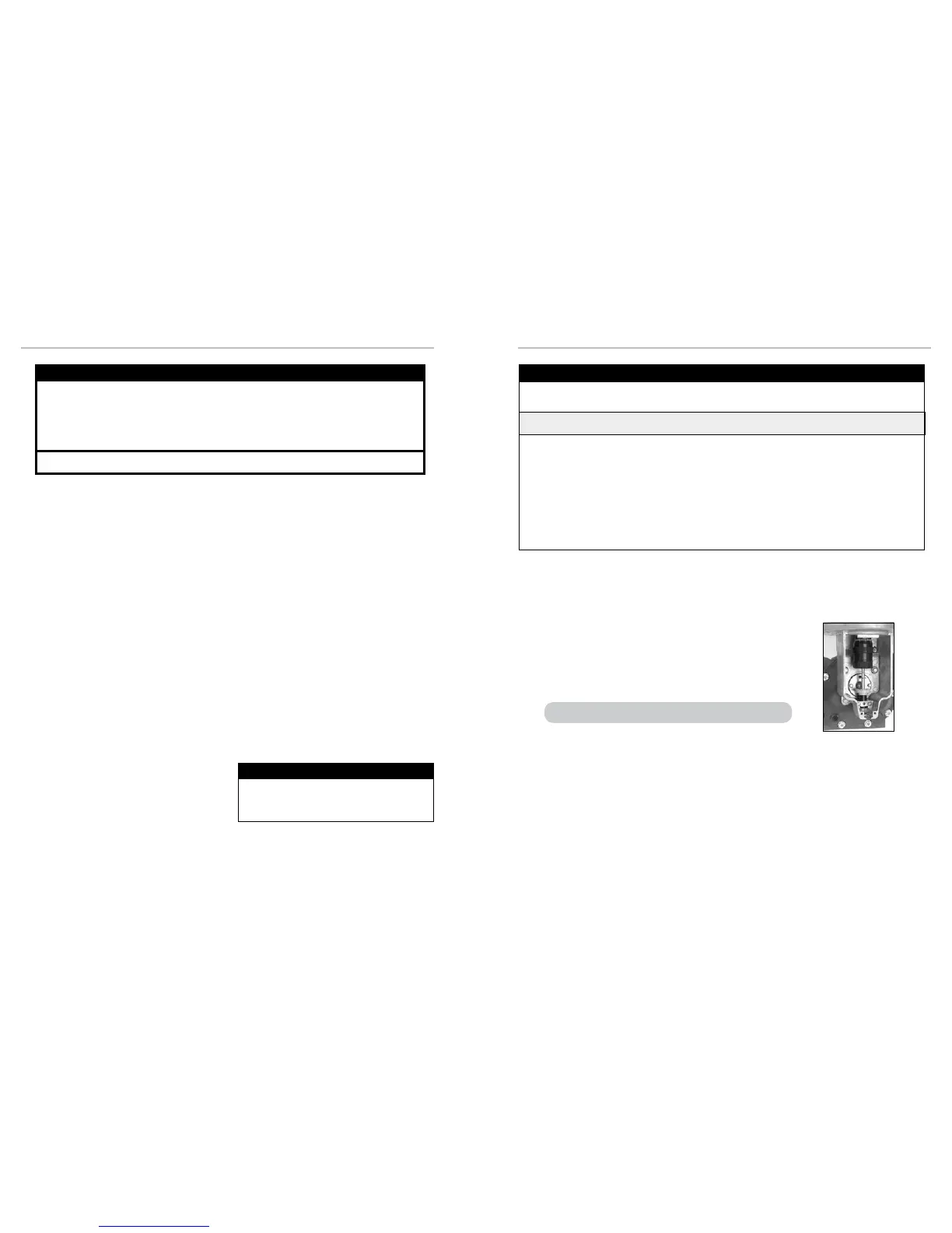
1. Cut the dust cover seal wire with side cutters.
2. Remove the dust cover screws with a 5/16’ wrench or slotted screwdriver.
3. Remove the dust cover.
See Relieving Internal Pressure above and the safety procedures on page 3.
All internal pressure must be relieved to zero pressure before disassembly or inspection of the strainer, vapor eliminator, any
valves in the system, the packing gland, and the front or rear covers.
3
Meters
6. Slowly crack the tting on top of the differential valve to
relieve product pressure in the system. Product will drain
from the meter system.
7. As product is bleeding from the differential valve, slowly
reopen and close the valve/nozzle on the discharge line.
Repeat this step until the product stops draining from the
differential valve and discharge line valve/nozzle.
8. Leave the discharge line valve/nozzle open while working
on the system.
1. Close the belly valve of the supply tank.
2. Close the valve on the vapor return line.
3. Close the manual valve in the supply line on the inlet
side of the meter. If no manual valve exists on the inlet
side, consult the truck manufacturer for procedures to
depressurize the system.
4. Slowly open the valve/nozzle at the end of the supply
line.
5. After product has bled off, close the valve/nozzle at the
end of the supply line.
Serious injury or death from fire or explosion could result in performing maintenance on an
improperly depressurized and evacuated system.
! WARNING
Liquid Controls disclaims all liability for damage to
meter or accessories because of corrosion, salting
out of product, or separation of chemicals whether
occurring during periods of use or storage.
DISCLAIMER
13
12

 Loading...

