REVERSING THE METER REGISTRATION
The direction of ow is specied by the customer when the meter is ordered. The standard direction of ow, facing the
front of the meter, from left to right. A red tag labelled “inlet”, afxed to the meter before shipment, indicates the inlet
side of the meter.
If the meter is equipped with a strainer, air eliminator, and/or valve, each component must be moved to the correct
side of the meter when reversing the direction of ow. The strainer and air eliminator should always be located on the
inlet side of the meter. Valves should always be located on the outlet side of the meter. Some parts of the valve may
require repositioning. See the valve’s manual for more information.
When the meter is rst installed, check the register. If the register counts down, meaning that the register numbers
decrease rather than increase, you must reverse the position of the adjuster drive gear.
To reverse the drive to the register, the position of the adjuster drive gear relative to the pinion gear of the packing
gland must be ipped.
1. Remove the dust cover. See Removing the Dust Cover on page 13.
2. Remove the retaining ring (4) with a screwdriver or pliers.
3. Remove the two retaining spring screws (1) with a standard
screwdriver.
4. Remove the retaining spring (2).
5. Remove the drive shaft (3) with the adjuster drive gear assembly
including (4) Retaining Ring and (5) Adjuster Drive Gear.
6. Remove the adjuster drive gear (5) and turn it 180° so that it is upside
down from the original installation position. The bushing (7) supports
the adjuster drive gear in the lower position. The retaining ring (4)
supports the adjuster drive gear in the upper position.
7. Reassemble the parts in reverse order. Make sure that the adjuster
drive gear meshes with the packing gland’s pinion gear (6) without
being too tight. There should be a little play in the gear teeth. The
retaining ring (4) should be placed in the groove provided on the drive
shaft (3), regardless of the adjuster drive gear position. The packing
gland pinion gear to adjuster drive gear ratio is either 1:1 or 2:1. In the
2:1 ratio, the pinion of the packing gland is smaller in diameter.
Adjuster drive gear engaged at topAdjuster drive gear engaged at bottom
1. Remove the dust cover. See Removing the Dust Cover on
page 13.
2. Check meter registration by delivering product to a reliable,
accurate prover. Perform multiple delivery tests to verify the
meter repeatability.
3. Record the setting indicated on the adjuster:
4. Note the difference between the volume of the prover and the volume indicated on the meter counter.
Calculate the % correction required using the formula below.
These instructions apply to meters equipped with mechanical
output accessories only. If your meter is equipped with an
electrical output (i.e., electronic pulser), refer to the manual
for the electrical component your Owner’s Information Packet.
Mechanical Instructions Only
SETTING THE STANDARD ADJUSTER
% Correction = x 100
Volume in prover - Volume on meter counter
Volume in prover
For M-15, M-25, M-30, and M-40 models, loosen the single set screw.
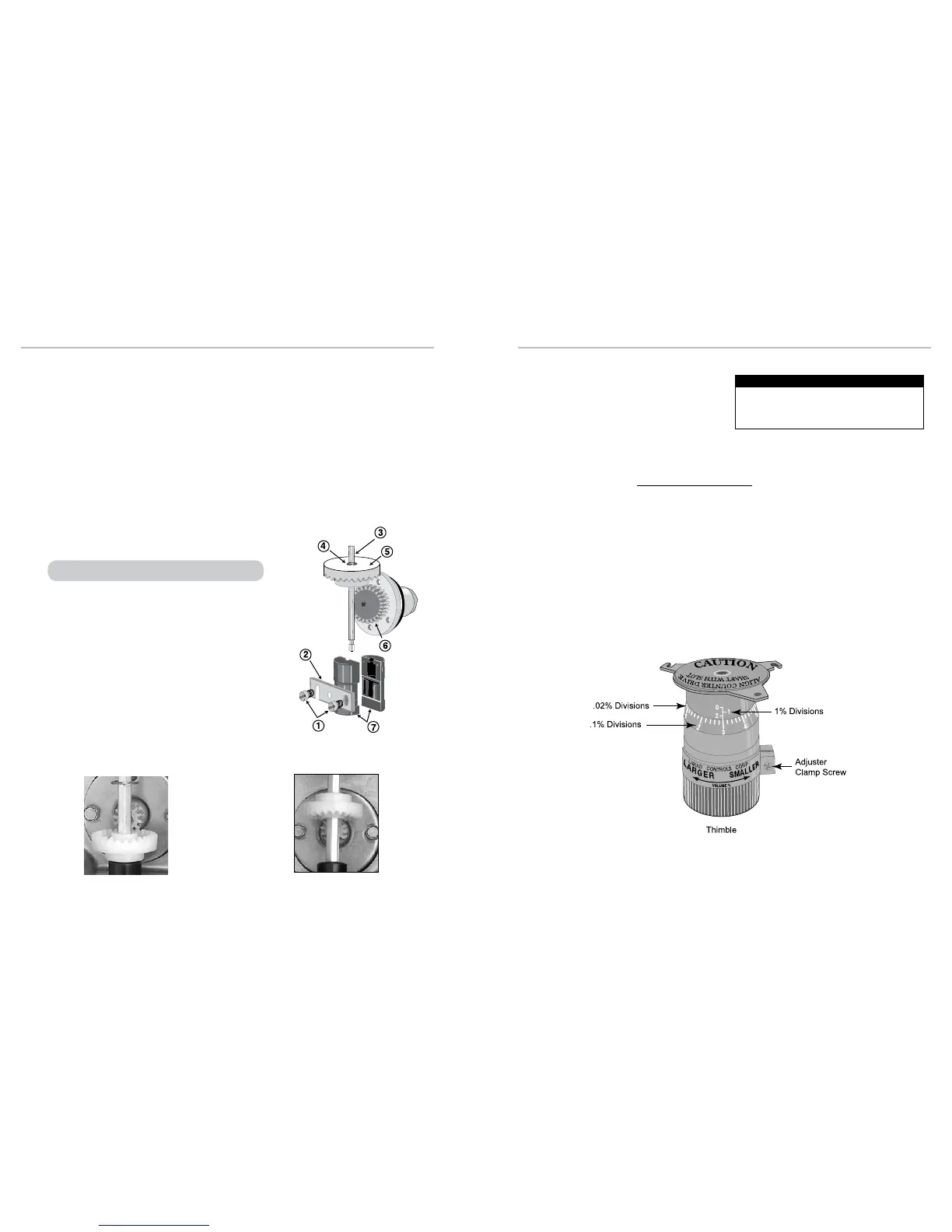
5. Loosen the adjuster clamp screw.
6. When the prover volume is less than the meter counter volume, add the percentage to the original adjuster setting by turning
the thimble towards the arrow marked larger (volume). Correct the original setting by approaching the number desired from the
next larger number. For example, if the desired adjuster setting is 2.4, turn the adjuster thimble to the left to number 5, then to
the right to obtain the 2.4 setting. Adjuster is currently set at 2.3 in the illustration below.
7. When the prover volume is more than the meter counter volume, subtract the percentage from the original adjuster setting by
turning the thimble in the direction of the arrow marked smaller volume percent.
8. Retighten the adjuster clamp screw. Run product through the meter to allow the adjuster to take a set. Then make several
prover runs to check for accuracy
11
10

 Loading...

