1. Push the O-ring (1) into the groove (2) on the front of the
meter housing.
2. Fasten the front cover (3) to the housing with the cover
screws (4) using the cover socket or open end/box end
wrench.
3. Screw the front drain plug (6) into the front drain plug hole
(7) using the drain plug allen wrench.
4. Push the O-ring (8) into the groove (9) on the rear of the
meter housing.
5. Fasten the rear cover (10) with the cover screws (11)
using the cover socket or open end/box end wrench.
6. Screw the rear drain plug (not shown) into the rear drain
plug hole using the drain plug allen wrench.
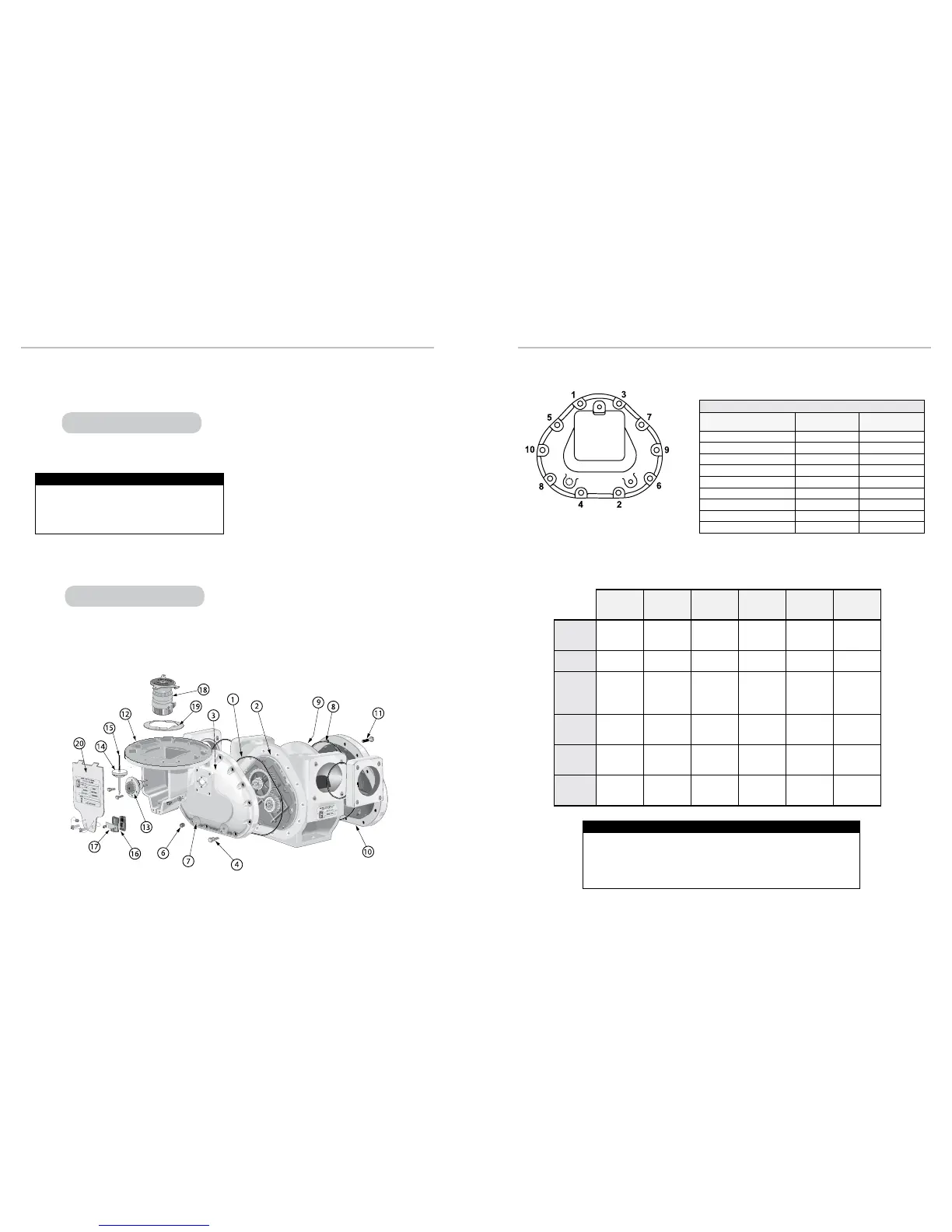
Meter Assembly Exploded View
Grade 5 Fasteners
Bolt Size
Foot-Pounds
NOMINAL*
Newton-Meter
NOMINAL*
#8 (.164) - 32 UNC-2A
2.54 (30.5 in/lb) 3.4
#10 (.190) - 24 UNC-2A
3.75 (45 in/lb) 5.1
1/4” (.250) - 20 UNC-2A
7.3 9.9
5/16” (.3125) - 18 UNC-2A
15.3 20.7
3/8” (.375) - 16 UNC-2A
27 37
7/16” (.4375) - 14 UNC-2A
43 58
1/2” (.500) - 13 UNC-2A
66 90
5/8” (.625) - 11 UNC-2A
132 179
3/4” (.750) - 10 UNC-2A
233 316
*Torque Tolerance is ± 10%
REASSEMBLING THE METER REASSEMBLING THE METER
MA-4
M-5
MA-5
M-7
MA-7
M-10
M-15
M-25
MA-15
M-30
M-40
M-60
M-80
Dust
Cover
Screws
⁵⁄₁₆” hex
wrench
⁵⁄₁₆” hex
wrench
slotted
screwdriver
slotted
screwdriver
slotted
screwdriver
slotted
screwdriver
Drain
Plug
¼” Allen
wrench
¼” Allen
wrench
³⁄₈” Allen
wrench
³⁄₈” Allen
wrench
³⁄₈” Allen
wrench
³⁄₈” Allen
wrench
Meter
Cover
Screws
½” hex
wrench/
socket
½” hex
wrench/
socket
¼” Allen
or
½” hex
wrench/
socket
¼” Allen
or
½” hex
wrench/
socket
⁹⁄₁₆” hex
wrench/
socket
¾” hex
wrench/
socket
Counter
Bracket
Screws
³⁄₈” hex
wrench/
socket
³⁄₈” hex
wrench/
socket
N/A
³⁄₈” hex
wrench/
socket
N/A
³⁄₈” hex
wrench/
socket
Bearing
Plate
Screws
⁵⁄₁₆” hex
wrench/
socket
⁵⁄₁₆” hex
wrench/
socket
⁵⁄₁₆” hex
wrench/
socket
⁵⁄₁₆” hex
wrench/
socket
⁷⁄₁₆” hex
wrench/
socket
½” hex
wrench/
socket
Rotor
Gear
Screws
⁵⁄₁₆” hex
wrench/
socket
³⁄₈” hex
wrench/
socket
³⁄₁₆” Allen
wrench
³⁄₁₆” Allen
wrench
³⁄₁₆” Allen
wrench
³⁄₁₆" Allen
wrench
Please apply these techniques when repairing meters in the eld.
1. Prior to installation, apply a small amount of Locquic Primer N764 to each screw.
2. Apply a light coat of Loctite 242 in three even strokes to each screw. The Loctite
and Locquic primer are not to be applied to the female connection in the rotor.
ROTOR GEAR SCREWS
LC recommends tightening the front and rear cover screws
in a criss-cross or “star” pattern with a minimum of two
passes. First pass should be at half-torque. Final pass(es)
should be at full torque. This method will ensure uniform seal
compression on cover O-ring or gasket. See page 21.
Tightening Front and Rear Covers
M-60 and M-80 models use a at gasket.
M-60 and M-80 models use a at gasket.
7. Screw the counter bracket (12) onto the front cover using
the counter bracket screws.
8. Insert the packing gland assembly (13) through the
counter bracket and into the cover plate. Make sure the
forks of the packing gland drive are in the slots of the
packing gland driver attached to the blocking rotor gear.
9. Screw the packing gland retaining plate onto the
counter bracket using the two retaining plate screws.
See Servicing the Packing Gland on page 15 for more
information.
10. Return the adjuster drive gear (14), the adjuster drive
shaft (15), and the drive shaft bushing (16) to the inside
of the counter bracket. Make sure the drive gear is in its
original position. See Reversing the Meter Registration on
page 10 for more information.
11. Screw the retaining spring (17) over the drive shaft
bushing and slide the retaining ring back into the slot on
the drive shaft.
12. Screw the standard adjuster (18) onto the adjuster
mounting plate (19).
13. Insert the standard adjuster and adjuster mounting plate
through the top of the counter bracket and onto the
adjuster drive shaft. Screw the mounting plate onto the
counter bracket.
14. Screw the dust cover onto the counter bracket using the
dust cover screws.
21
20

 Loading...

