30
4.0 Start-Up
4.1 Cooling Tower Installation
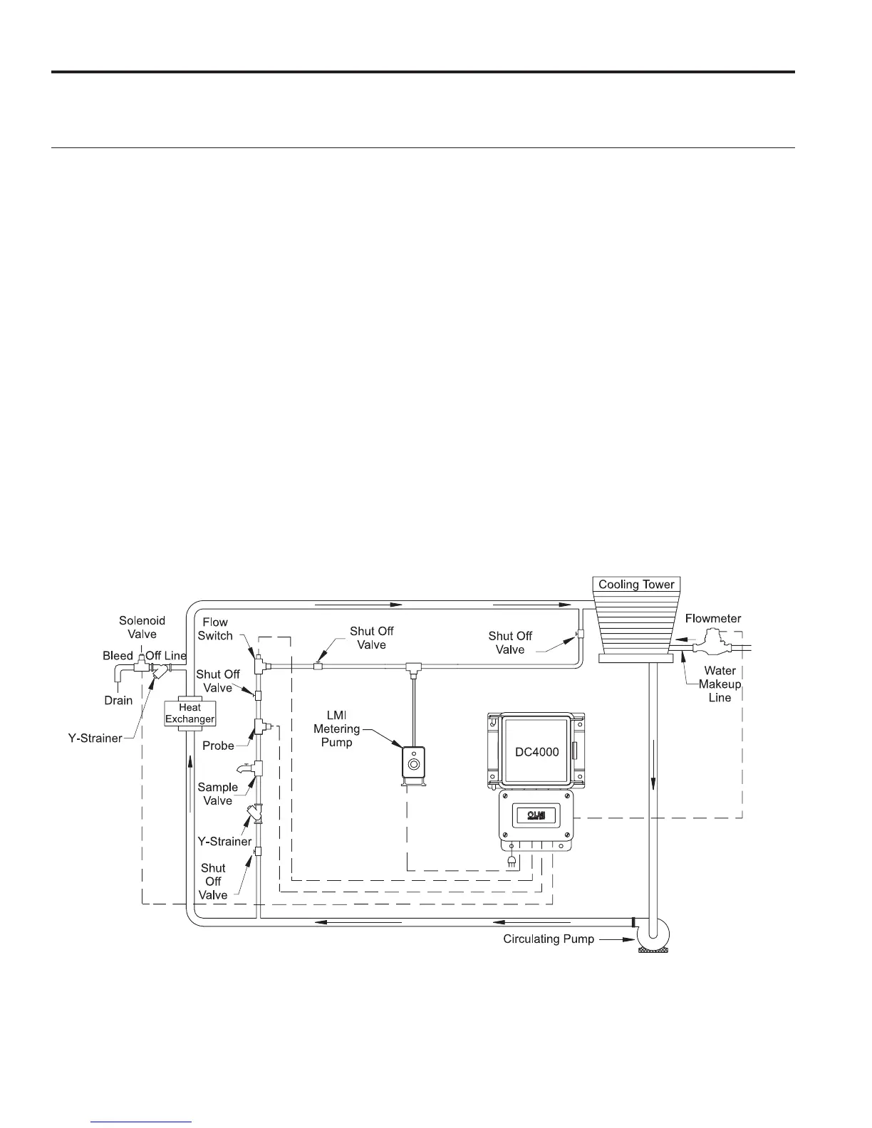
The DC4000 Series of conductivity controller should be installed based upon the recommended system diagram below.
A bypass loop for open recirculating water systems is the best method of conductivity monitoring and control.
The conductivity sensing electrode used with the conductivity controller must receive an active representative sample
of system water. The electrode should be installed so that it is removed horizontally from its mounting tee. Water ow
should enter from the bottom of the conductivity tee and exit out the top. This type of installation insures that the elec-
trode tee is full of water whenever system ow is on and that the probe is fully emersed. This prevents the electrode
from becoming air bound.
System shut off/isolation valves are recommended for installation on either side of the conductivity sensing electrode.
This allows for ease of system isolation and electrode removal. A sample cock valve and a stainer are recommended to
allow for periodic water sampling and water ltering.
Injection of required water treatment chemicals can be effected directly into the bypass line. When chemicals are injected
into the bypass line, they should be downstream of the conductivity sensing electrode to avoid interference with readings.
An installed ow switch is recommended for the bypass line to allow for disabling of controller/pump operation during
system maintenance or repair.
Figure 6: Cooling Tower Installation Diagram
(866) 433-6682 • (281) 359-8538 • sales@novatech-usa.com • www.novatech-usa.com
 Loading...