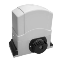
Gate Opener 1
Step 1
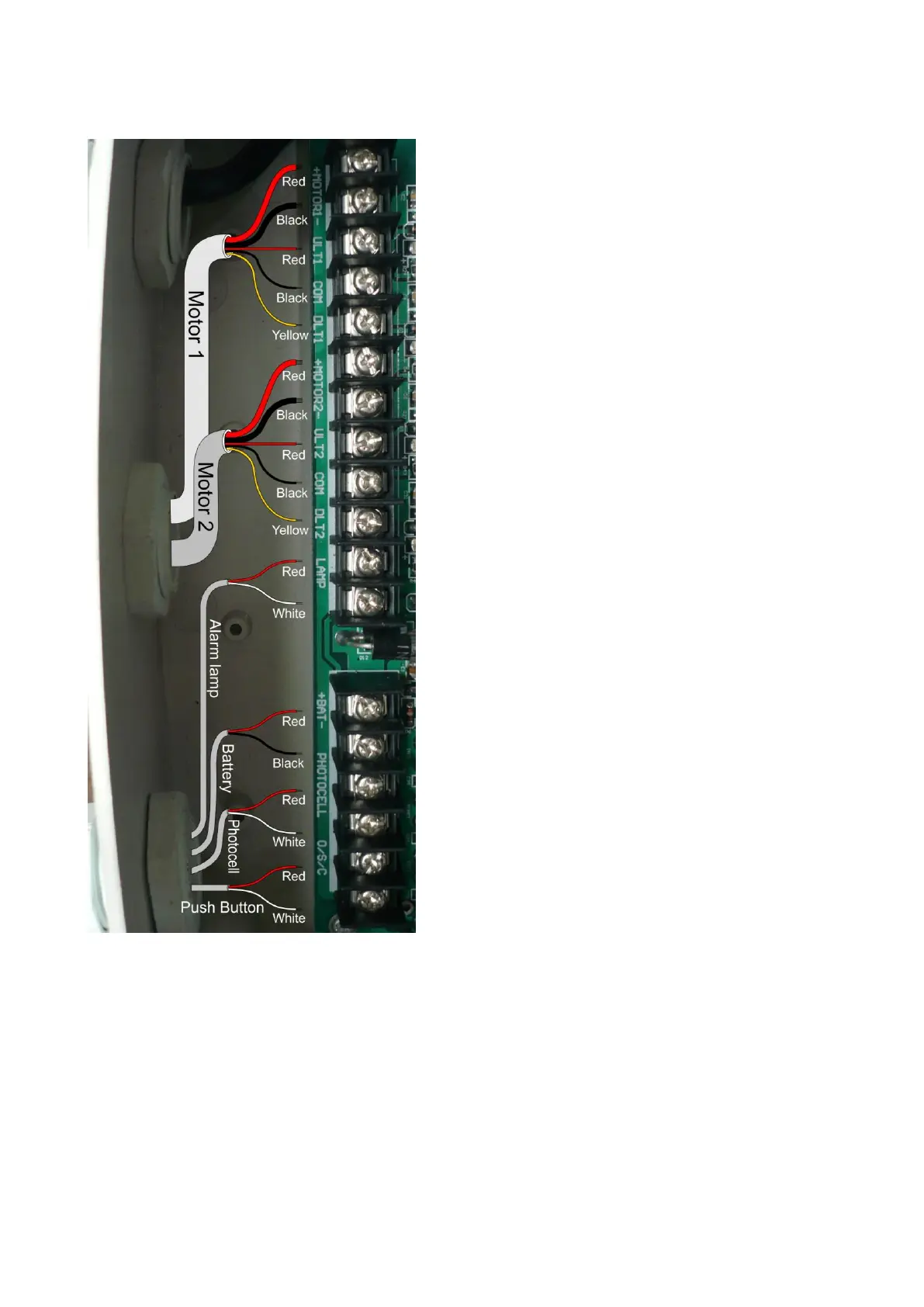
Insert the stripped cable wires into the
appropriate terminals on the opener terminals
block. The red thick wire should be inserted
into the MOTOR1+ terminal, the black thick
wire into MOTOR1-, the red wire into ULT1,
the black wire into COM, and the yellow wire
into DLT1 terminal.
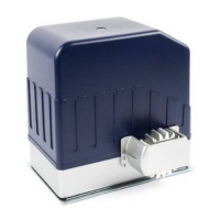
Gate Opener 2
Step 2
Similar as the step 1, insert the stripped cable
wires into the appropriate terminals on the
opener terminals block. The red thick wire
should be inserted into the MOTOR2+
terminal, the black thick wire into MOTOR2-,
the red wire into ULT2, the black wire into
COM, and the yellow wire into DLT2 terminal.
NOTE: It is recommended that Gate Opener
1 is installed in the Master Gate, and Gate
Opener 2 is installed in the Slave Gate.
Alarm Lamp (optional)
Step 3
The red wire should be inserted into either
LAMP terminal, the white wire into the other
one.