Indicate Illustration on the Digital Display When Gate
Opener is Running
The left mark on Digital Display symbolizes motor of gate opener 1 when the gate opener is running. The
right mark on Digital Display symbolizes motor of gate opener 2.
When the motor is run to gate -open direction or gate -close direction, the mark on Digital Display
indicates “n” or “u” respectively.
When the motor is running, the Digital Display indicates “-”.
When Gate Opener 2 is set as Master gate (i.e. when “10” indicated at P2 set mode in the Control
Board), the Digital Display flashes “-n” before TTC time is up.
Adjust the Limit Switch
Step 13
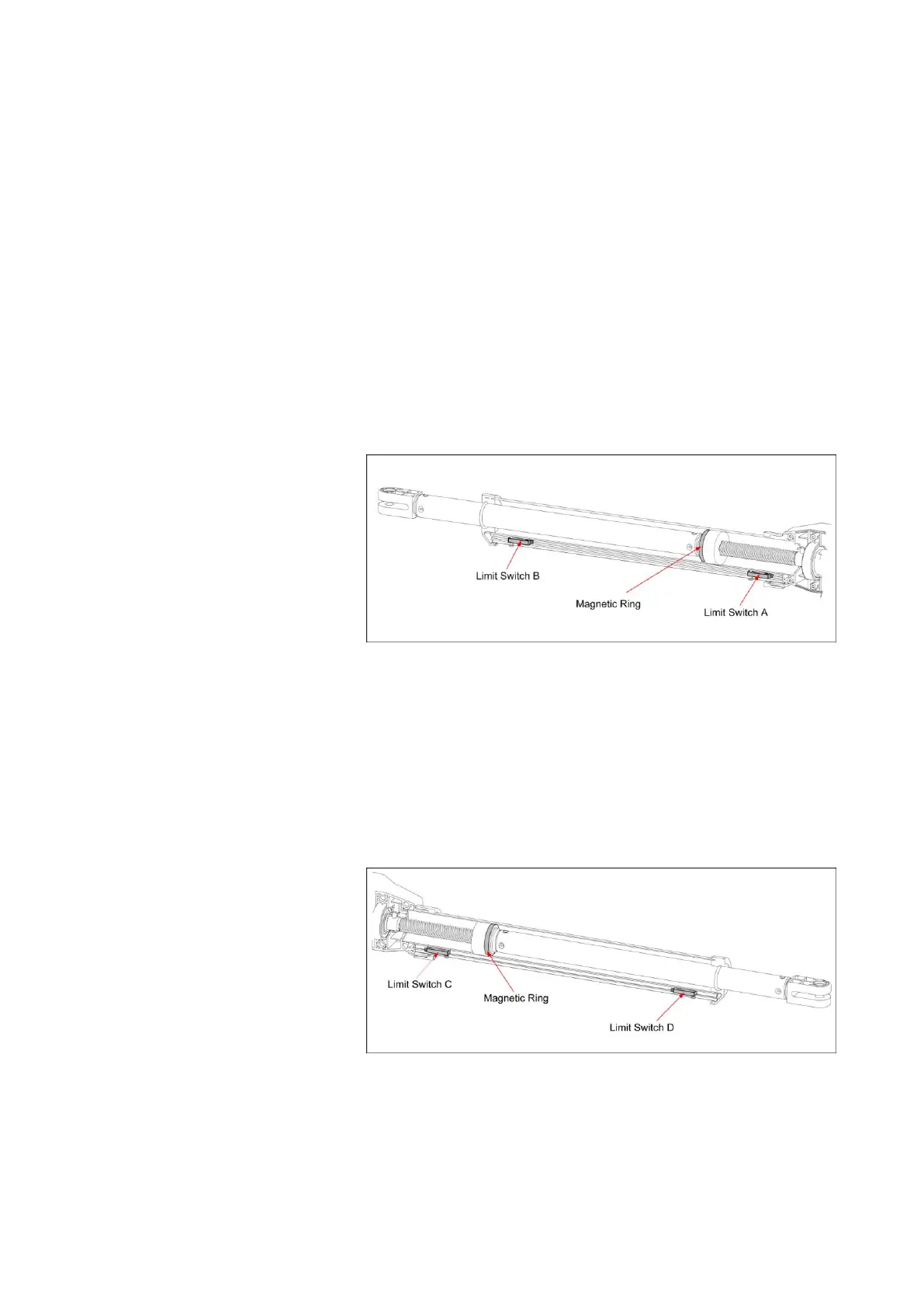
Adjust the Limit Switch of Arm 1
Pull Gate 1 to its fully open position. Use a cross point screwdriver to unscrew Limit Switch A and slide it
to the desired position. Then fix the Limit Switch A.
Pull Gate 1 to its fully closed position. Use a cross point screwdriver to unscrew Limit Switch B and slide
it to the desired position. Then fix the Limit Switch B.
Limit setting for Gate 1 is finished.
NOTE: Always place the magnetic ring between the Limit Switch A and B.
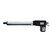
Step 14
Adjust the Limit Switch of Arm 2
The adjusting procedures are similar as in Step 13.