26
2.1 Displays, Operating Elements and Connections
☞
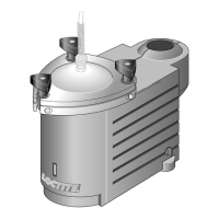
● See the illustration on page 3.
1 Cover
2 Cover screw fasteners
3 Product connection 1/4“ (for 1/4“ product hose)
The 3/8“ product connection together with a 3/8“ product hose is included with the dispensing valve.
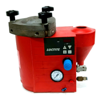
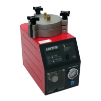
4 LED indicators, analog (automatic reservoir only)
2 green LED’s = As long as one of these LED’s lights, adequate product is available in the bottle.
7 yellow LED’s = Refill.
If one of these LED’s lights, the next bottle of adhesive should be prepared for use.
The farther down the lit LED is, the less product is available.
1 red LED = Empty.
The automatic reservoir is automatically depressurized by the controller 97102 or
97103 and can be automatically repressurized only after the replacement of the
empty product bottle with a full one (see Section 5.3).
5 Depressurizing valve
Valve position – The reservoir is depressurized.
Valve position – The reservoir can be pressurized.
6 Socket XS2/OUT (automatic reservoir only)
With the connection of two automatic reservoirs on a controller 97103, the automatic reservoir B is
connected here.
7 Equipment connector XS2/IN (automatic reservoir only)
The controller 97102 or 97103 is connected here.
8 Pneumatic connection P in
Connection for the external pneumatic supply.
Description2