DYNAMIC MOTION SYSTEM - SYSTEM MANUAL // PAGE 14
4.3 ASSEMBLY: BENCHING TABLE SYSTEM
This chapter describes how to assemble a Benching Table System. In a Benching System, multiple tables are
connected to one Power Hub via one or more Beching Adapters. The tables are operated separately. You will
need one User Interface for each table. The Benching Adapter works like a power distributor. A Benching
Table System consists of between two and six tables. The Actuators within a single table are operated simul-
taneously by one User Interface. The Table Top and Height-Adjustable Columns are supplied by the Reseller.
4.3.1 REQUIRED COMPONENTS
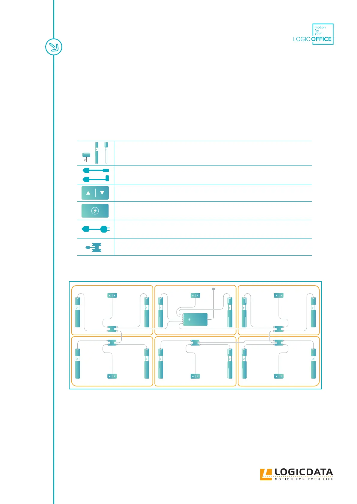
Up to 12 Height-Adjustable Columns with DYNAMIC MOTION Actuators
1 DMLIN Actuator Cable per Actuator
2 to 4 User Interfaces
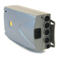
1 Power Hub
1 Power Cable
1 to 5 Bench Adapters
4.3.2 CONNECTING THE COMPONENTS
DMP360
Fig. 4: Connection map (Benching Table System, 6 tables, each with 2 Height-Adjustable
Columns, powered by the DMP360). Note: This is the largest possible conguration.
Table with the Power Hub:
1. Plug the Actuators into the Power Hub
2. Plug the User Interface into the Power Hub