TOUCH FAMILY - OPERATING MANUAL // PAGE 18
6.2 ASSEMBLY: TOUCHfx
6.2.1 REQUIRED COMPONENTS
1 TOUCHfx
2 2 Mounting Screws (supplied by Reseller)
Tool Screwdriver
INFO
Screw specications
Thread diameter: max. 5 mm | Head diameter: 8.5 mm - 10.6 mm
If possible, do not use countersunk-head screws.
6.2.2 PROCESS
1. Position the Handset under the table top and mark the position of the drilling holes. If necessary,
use the Drilling Template in chapter 5.3.1 to help you.
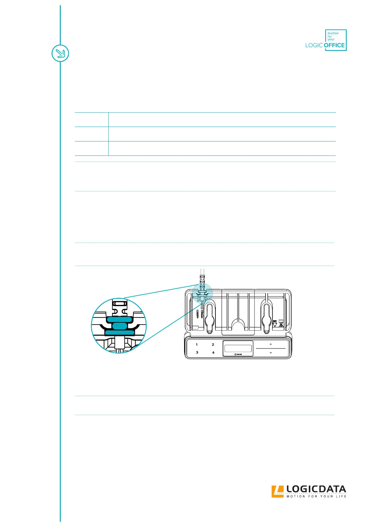
2. Insert the Strain Relief into the designated slot on the Handset (Fig. 6).
NOTICE Inserting the Strain Relief incorrectly may cause damage to the Cable and Handset.
Ensure that the Cable does not protrude over the housing
Fig. 10: Inserting the TOUCHfx Strain Relief
3. Use the screwdriver and 2 Mounting Screws to attach the Handset to the Table Top at the
marked drilling points.
NOTICE
The required tightening torque depends on the material of the Table Top. Do not exceed
2 Nm.
6.2.3 COMPLETING ASSEMBLY
After the TOUCHfx is attached to the Table Top, you must connect the Cable to the Control Box. Refer to the
manual for your chosen Control Box for instructions.