44
COMPILER TECO/ATL
REG. CODE
1-5302-296
MODEL N°
50510
DATE OF ISSUE
01.89
REVISION 02
ENDORSED
DATE
17.04.2003
105
103
104
VIII
Starting with electronic speed governor
(see lay-out on page 43)
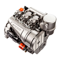
In position 0 the engine is not working and no part is energized. The
rack rod is in stop position (retained by two springs 10 inside
actuator A).
By rotating key C to position 2 the electromagnet withdraws allowing
the rack rod to reach ìts highest delivery being connected to the
actuator at its max. ievel of energization. When the engine,
immediately after starting, reaches 1000 r.p.m, the controller
reduces the actuator position, after 1 second switches off the
electromagnet T and after more 0.5 seconds returns at his normal
position with the engine speed set as per position of potentiometer
P1.
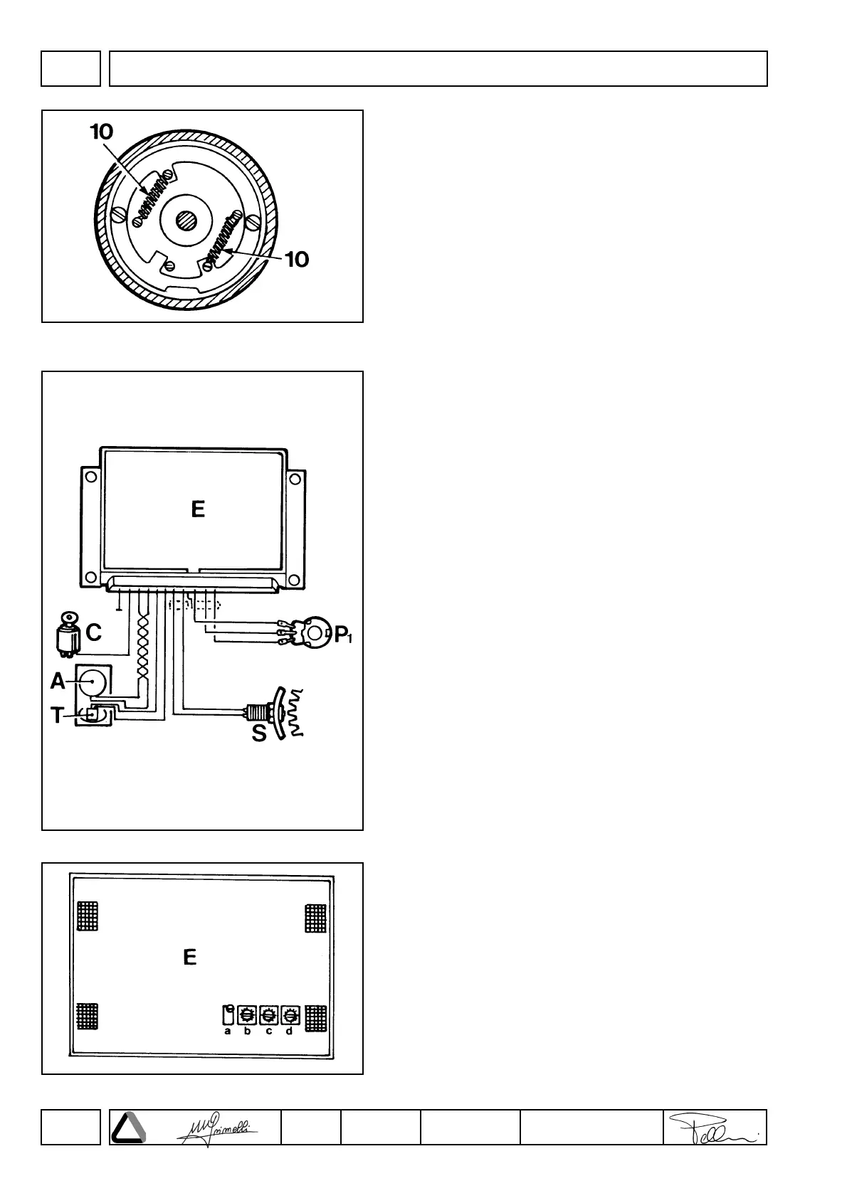
Engine running with electronic speed governor
The engine starts running at the pre-set speed.
Potentiometer P is located either inside the control box E or on
control panel P1.
In case of an external potentiometer P1 the engine speed can be set
at any point between the idling and full speed in on-load conditions
(setting performed on the control box in the test room).
The electronic control box E controls actuator A (by sending or cutting
off the power supply) to keep the speed set through P1 constant
independently of the absorbed load.
Control box E prevents the engine from starting (or stops it) in case
of no power supply or in case connection with r.p.m. sensor S is
broken (or short-circuited).
Electronic speed governor control box
Control box E features four setscrews which must be positioned on
the test bed (torque dynamometer) along wilh the engine.
a) Setscrew for speed control (r.p.m.)
b) Setscrew for sensitivity adiustment when the engine is
running at full speed.
c) Setscrew tor sensitivity adjustment at low speed.
d) Setscrew for extra fuel release; once correctly positioned, this
setscrew is generally sealed.
DISASSEMBLY/REASSEMBLY
 Loading...