54
COMPILER TECO/ATL
REG. CODE
1-5302-296
MODEL N°
50510
DATE OF ISSUE
01.89
REVISION 02
ENDORSED
DATE
17.04.2003
140 141
138
139
X
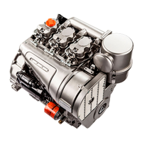
Injection timing reference marks on crankcase and flywheel
A = Piston reference mark al the top dead centre
B = Injection timing reference mark compared to A
(A - B) = Distance in mm.
C = Piston reference mark in injection tíming position.
αα
αα
α = Reference angle in degrees
Values given in mm.. have been detected al the periphery of a
standard flywheel with 288 mm diameter.
For engines set at 3000 r.p.m.
For engines set at 1500÷2000 r.p.m.
For engines set at 3000 r.p.m.
Note: The clear difference in static injection timing between engines
type 11 LD535-3, 11 LD625-3 and 11 LD626-3 is lo be found in the
special plunger machining found in the latter. See page 50.
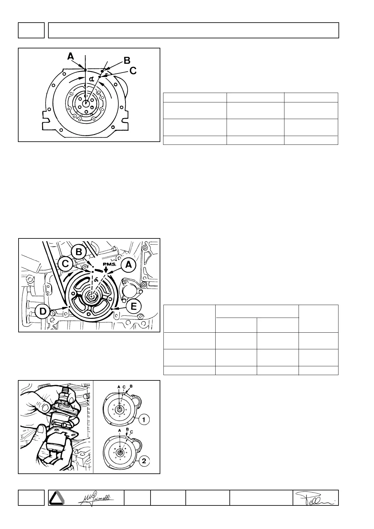
Injection timing reference marks on the pulley and the gear cover
A = Gear cover reference arrow al top dead center P.M.S. (T.D.C.),
obtained with a casting process.
B = Injection timing mark with reference to A
(A - B) Distance in mm.
C, D, E Injection timing mark or top dead center for the
individual pistons
a = Reference angle in degrees
Injection timing correction
If reference mark C does not match with B follow examples 1 and 2.
1 Example of late injection timing: remove shims under the pump lo
make C match with B.
2 Example of early injection timing: add shìms under the pump to
make C match with B.
Note: By adding or removing a 0.1 mm shìm under the pump C is
delayed or advanced by approximately 3 mm.
FUEL SYSTEM
(A÷B) mm *
60÷65
55÷60
37÷42
α
24°÷26°
22°÷24°
15°÷17°
Engine type
11LD535-3
11LD625-3
11LD535-3
11LD625-3
11LD626-3
∗∗
∗∗∗
∗∗∗∗
Engine type
11LD535-3
11LD625-3
11LD535-3
11LD625-3
11LD626-3
Pulley dia.
142 mm
29,7÷32,2
-
18,6÷21
Pulley dia.
163 mm
-
31÷34
-
(A÷B) mm
α
24°÷26°
22°÷24°
15°÷17°
 Loading...