Pc-Boards
- 25 -02.20 909.2710.1-06
Overview connectors DMRPP04
connector designation
X1 torch trigger switch
X2 front panel
X3 volt/amp display
X4 wire inch button
X5 tacho wire feed motor
X6 solenoid valve
X8 control cable (Interpass hose package)
X9 wire inch and retract button
X10 wire feed motor “-” (minus)
X11 wire feed motor “+” (plus)
X12 welding potential (PowerMaster signal compensation)
X13 control cable PushPull
X14 flat ribbon connector motor wires
X15 flat ribbon connector PWM control
X16 wire-end sensor
X17 PushPull motor
X18 remote control interface
X20 LorchNet (CAN bus)
Tab. 14: Connectors DMRPP04
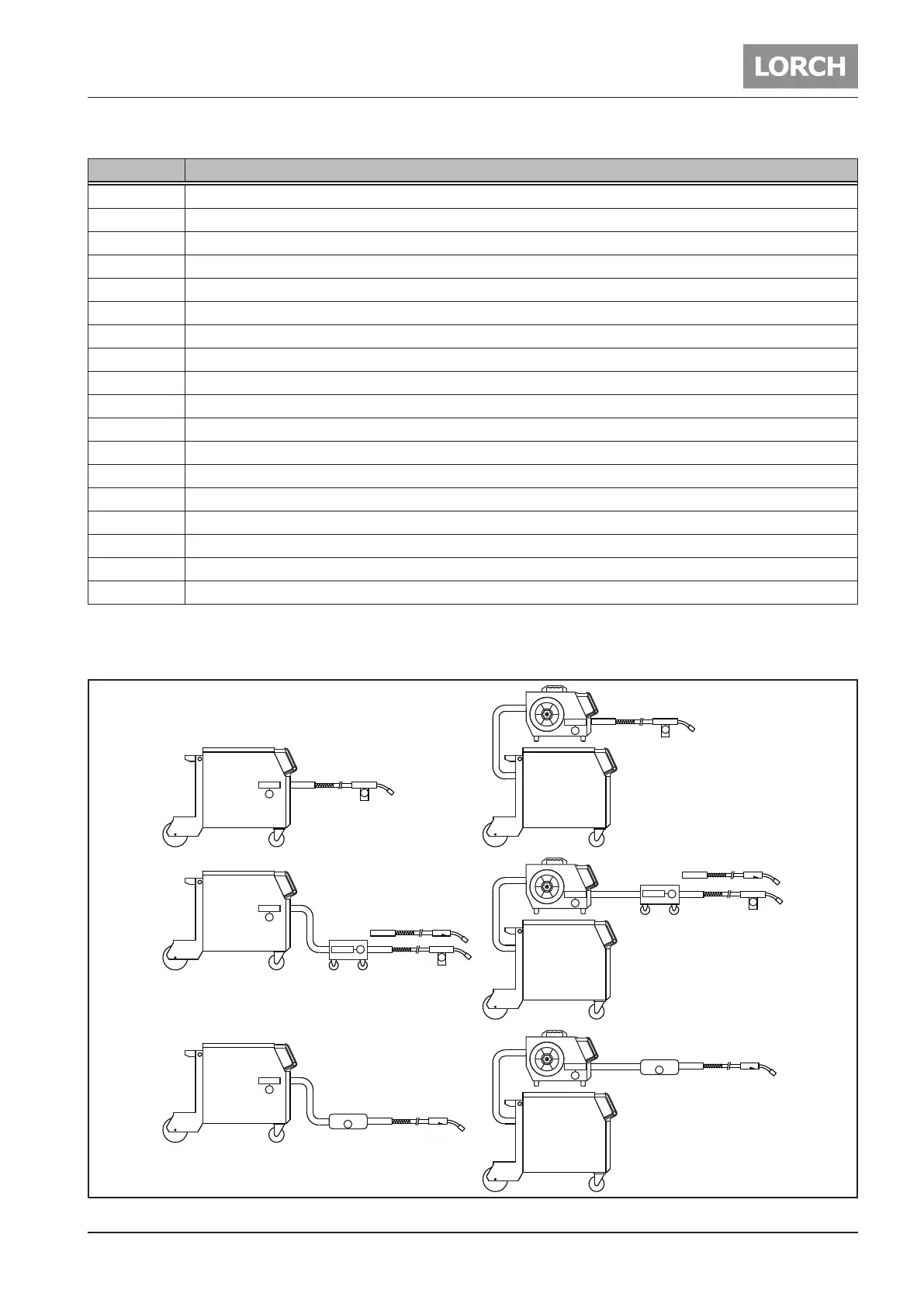
Overview PushPull, Intermediate Feeder, NanoFeeder
DMRPP
M
M
DMRPP
M
DMRPP
M
M
M
DMRPP
M
M
DMRPP
M
DMRPP
M
DMRPP
M
DMRPP
M
NanoFeeder
M
NanoFeeder
M
Fig. 12: Configurations PushPull, NanoFeeder, Intermediate Feeder