LOUP ELECTRONICS
•
1-877-489-5687
•
WWW.LOUPELECTRONICS.COM
7
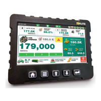
WIDTH & sEcTION sETuP
1. Select the number of sections
(up to 12 possible)
2. Starting with Section 1, enter the last
population sensor number installed on that section followed by
the width for that section.
Example: If installing 6 population sensors on a 30, 3-section
folding drill, the last row number for section 1
would be “Row 2”, section 2 would be “Row 4” and
section 3 as “Row 6”. Each Section Width would be
10.
Note: e Row Number here is referring the number
assigned by the Loup Elite monitor when sensor was
learned. Row numbers can be learned in dierent
ways such as sequencial order (1-6) or to match the
physical row number on a drill (1, 16, 17, 32, 33, and
48).
3. Select the “Next Section” button to scroll to the next section.
Repeat steps 1 & 2. Each Section width will contribute to the
overall implement width.
When all sections are setup, check that the total width is
correct and Select “Exit & Save”.
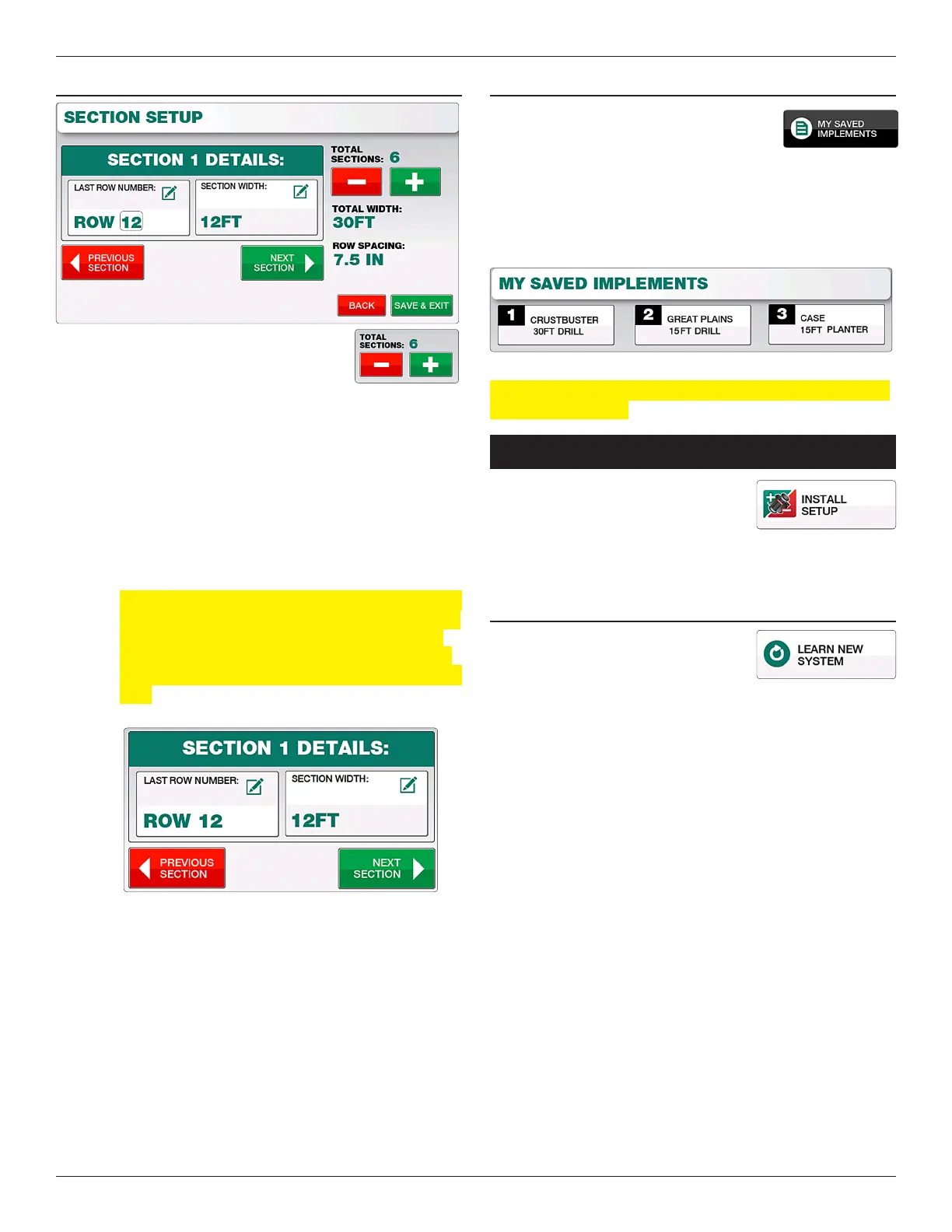
cHANgINg IMPLEMENTs
Up to three separate implements can be
selected on the Loup Elite. Unless pre-
congured by Loup, all three implements
will default as gravity drills. To switch implements simply select
the “My Saved Implements” button and select the implement
number you’d like. From here you can congure the type of
implement, make, width and so forth. All implement settings are
automatically saved as they are made.
Note: When selecting a dierent implement, the Elite console
needs to be restarted.
inSTall/SeTup Menu
Located by selecting “Menu” and “Install
Setup”. e Install/Setup Menu is used
to Learn a New system, Add new sensors
to your existing system or Remove specic sensors from your
implement.
LEARN NEW sysTEM
Select “Learn New System” if your
monitor did not come pre-programmed
or you wish to relearn all sensors.
1. Start by unplugging all sensors on the implement and then
selecting “Learn New System”. A popup will warn you that
all current sensors will be overwritten. Select “Yes, Learn
New System”.
2. e monitor will prompt you to Plug In Fbus sensors (all
us sensors have a 3 pin connector with white, black
and green wires) in the following order. e sensor being
prompted will automatically be learned upon connecting the
3 pin connector.
1. Speed Sensor: Sha mounted ground speed sensor
2. Li Switch
3. Rate Cal Sensor
4. Population/Row Sensors: Up to 32 sensors
5. Bin Level: Up to 6 bin level sensors
6. Sha Speed Sensor: Up to 6 possible Sha RPM
Sensors
7. Fan: Up to 3 Fan RPM sensors
8. Blockage Module: Up to 12 Modules with 192
runs of product detection.