LOUP ELECTRONICS
•
1-877-489-5687
•
WWW.LOUPELECTRONICS.COM
9
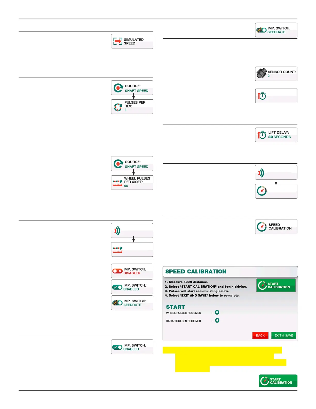
sIMuLATED sPEED
Allows you to enter a static speed into the
monitor without any other speed source.
For use in more unique conditions such as a
GPS/Radar failure, or other troubleshooting.
PuLsEs PER REVOLuTION
Available when “Sha Speed” is selected.
Pulses per Rev (Revolution) are the number
of magnets the implement mounted speed
sensor sees in one revolution of the sha
being monitored. For most applications this
number willl be 4.
To change, enter a new number into the keypad and select “Exit &
Save”.
WHEEL PuLsEs PER 400fT
Available when “Sha Speed” is selected. is
is the ground speed calibration number for a
implement mounted speed sensor.
e Default number is 90. To change, enter a
new number into the keypad and select “Exit
& Save”. Increasing this number will cause the monitor to show a
slower MPH, decreasing it causes the MPH to increase.
RADAR PuLsEs PER 400fT
Available when “Radar” source is selected.
is is the ground speed calibration number
for a radar speed sensor.
IMPLEMENT sWITcH
e implement switch sensor is used for
in/out of motion detection. e li sensor
is used when ground driven sha rotation
cannot be used or a variable rate drive as
common on air seeders is being used.
Each button push toggles this setting
between “Disabled”, “ Enabled”, and
“Seedrate”.
IMPLEMENT sWITcH ON
When a “Li Switch” sensor is learned
to the monitor, toggle the “Imp. Switch”
button to “Enabled”.
IMPLEMENT sWITcH
By sEEDRATE
When using the “Seedrate” mode, the monitor will wait to see
seed ow for a specied time accross a specied number of
population sensors before going in or out of motion.
Change the value for “Sensor Count” to
specify how many sensors of seedow are
needed for in/out of motion.
Change the value for “Seed Delay” to specify
how long seedow must be detected for in/
out of motion.
LIfT DELAy
When enabled, the Li Delay species the
seconds given to make a turn. is value can
range between 1 and 99 seconds.
sIMuLATED sPEED
Available when “Simulated Speed” is
selected as the source. Use this eld to enter
the static speed of your choice. e monitor
will continually display this speed at all
times until otherwise specied.
sPEED cALIBRATION
All new systems require a ground speed
calibration to ensure accurate population
readings, accurate area totals and accurate
ground speed readings. To complete the calibration, measure
a course 400 long preferably on level ground with a start and
nish point. e drill must be in the down position throughout
this procedure.
Note: During the calibration the monitor is looking for
the number of pulses produced from the drill
mounted sensor or in the case of radar, the number
of radar pulses.
1. Select the “Start Calibration” button
to begin.
15815
RADAR PULSES
PER 400FT
RADAR
SOURCE
3 SECONDS
SEED DELAY:
5.0 MPH
SPEED:
SIM. SPEED
SOURCE