Operation ProtoMat S
50 HB V0.9/Mrz-11 © 2011 LPKF AG
6
Pos: 21 /ED_Technisc he_Dokumentation/2_Be dienungsanleitun g/Maschine/RP_Fräsb ohrplotter/Pr otoMat_S_Serie/Pr otoMat_S_Serie_II G/Kapitel_6_Bedien ung/6_02_02_Bedienob erfläche_Circ uitPro @ 0\mod_1267182074 217_2058.docx @ 6460 @ 344
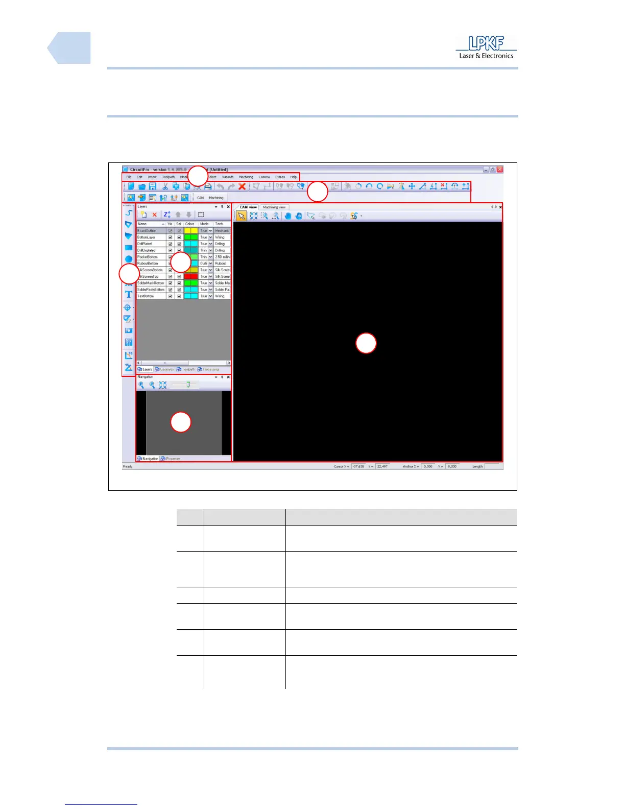
6.2.2 Grafical user interface
The CircuitPro user interface consists of several windows.
Fig. 19: User
interface
Tab. 9: User
interface
Nr. Display Function
/1/ Menu bar The individual program menus can be accessed via the
menu bar.
/2/ Function bar The function bar contains several functions for the control
of the circuit board plotter and modification of the
machining process.
/3/ Window Layer The window “Layer” lists the individual project layers.
/4/ Function bar
Insert
The function bar “Insert” contains several objects
which can be inserted into the project data.
/5/ Window
Navigation
The window “Navigation“ displays the actual
working area.
/6/ CAM View
The window “CAM View“ shows the project data.
The individual objects are highlighted in user
defined colours.
5
1
2
6
3
4