4 -21
Lift rod(LH) Lift rod(RH)
480~530 mm(CAT1)
(18.9 ~ 20.9in)(CAT1)
450~ 565 mm(CAT1)
(17.7 ~ 22.2in)(CAT1)
467~533 mm(CAT2)
(18.4 ~ 21.0in)(CAT2)
472~ 572 mm(CAT2)
(18.6 ~ 22.5in)(CAT2)
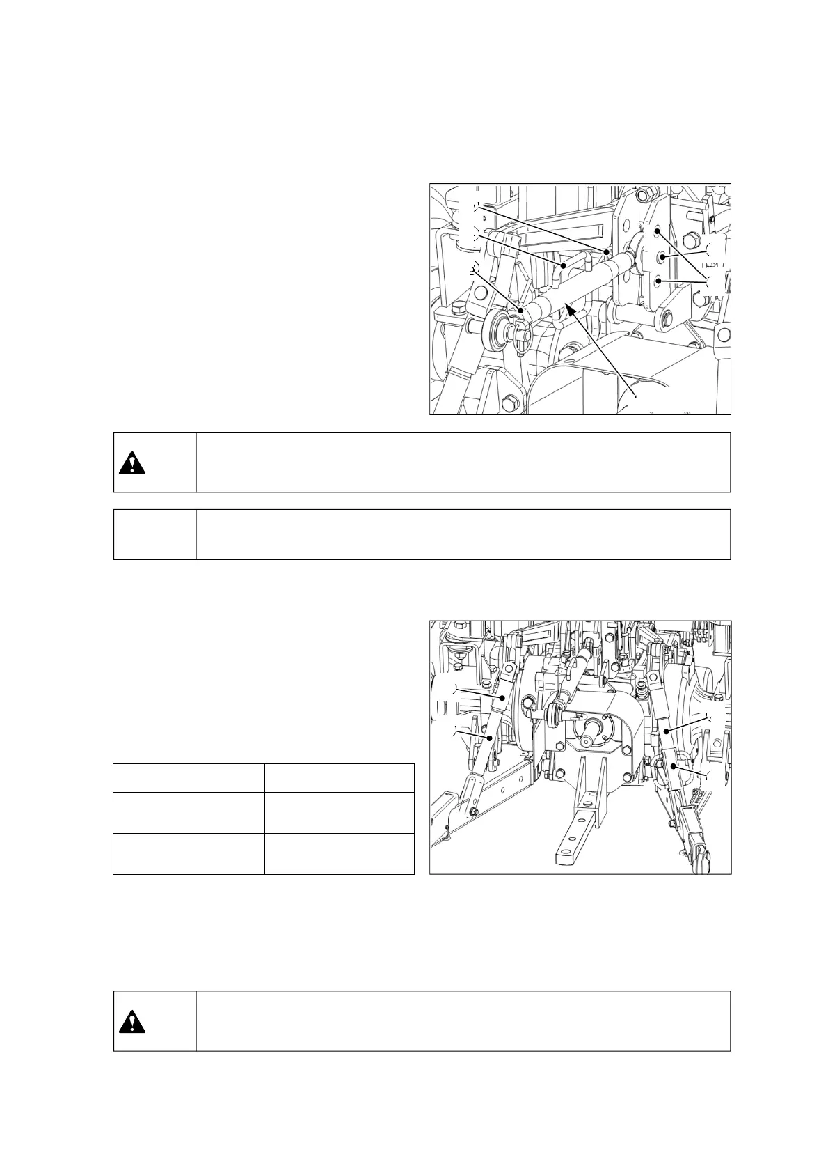
① Upper link installation and
adjustment
Select a suitable attaching hole(2) depending on
the draft load of the implement. The upper hole
is more sensible than lower one for draft load
control. (optional)
Adjust the length of the upper link with turning
the sleeve(4) after loosening locking nut(3).
Fasten the locking nut(3).
Adjustment range :
CAT1 : 430~654mm (16.9~25.7 in)
CAT2 : 534~784mm (21.0~30.9 in)
▶ Insert snap-pin(6) firmly to prevent the upper link pin(5) from being escaped.
Notice
② Adjustment of lift-rod (Left/Right)
For lift rod (LH), detach the upper side from the
lift arm and turn the upper side(1) left/right to
adjust the length.
For lift rod (RH), lift up the handle(4) and turn it
to the left or right to adjust the length. Lock the
lift rod handle to the lower part after adjusting.
⑥
④
②
⑤
③
Upper link
④
③
①
②
▶ Do not adjust the length of the upper link over the maximum limit. It may cause
fatal injury or death by falling object.
Caution
▶ Do not adjust the length of the lift-rod over the maximum limit. It may cause fatal
injury or death by falling object.
Caution
 Loading...