Chapter 7 - Options
156
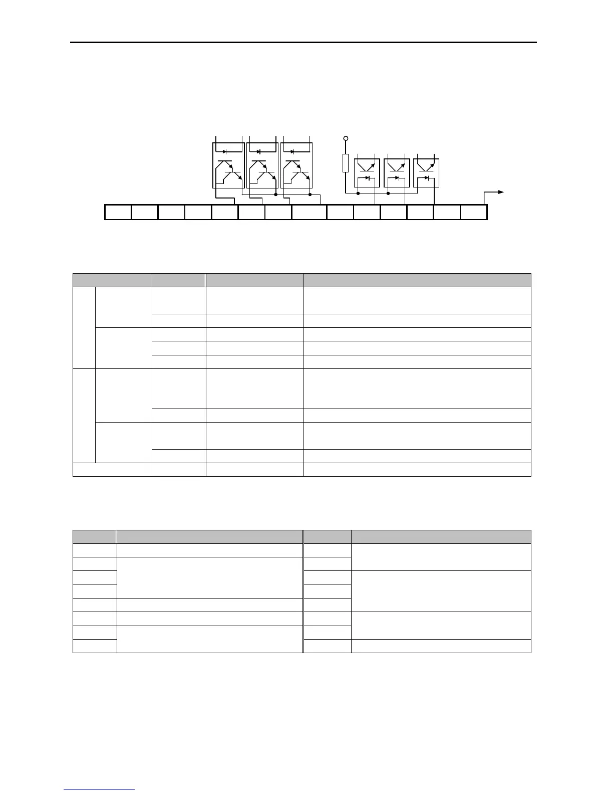
7.1.2 Terminal Configuration
VR
7.1.3 Terminal Description
Section Terminal Name Description
P4, P5, P6 Multi-Function Input
Used as the extended function of P1, P2, P3
(I/O-12 ~ I/O-14) Contact Input
CM Common Terminal Common terminal for P4, P5, P6
VR Power Supply for V2 DC voltage output terminal for V2 (+12V, 10mA)
V2 Analog Voltage Input Analog voltage input terminal for frequency reference or override.
Input
Analog
Frequency
Reference
5G Common Terminal Common terminal for VR and V2
LM Load Meter
Used to monitor one of Output F
requency, Output Current, Output
Voltage, DC link Voltage.
(+15V Pulse output, Average voltage: 0 ~ 10V DC)
+15V Pulse
Output
CM Common Terminal Common terminal for LM
Q1, Q2, Q3
Multi-Function Output
(Open-Collector Output)
Used as the extended function of AXA, AXC (I/O-44)
Output
Open Collector
Output
EXTG External Common Terminal
Common terminal for Q1, Q2, Q3
NC Not Used
7.1.4 Parameters of Sub-A Board
Code Parameter Description Code Parameter Description
EXT-01 Sub Board Type Display EXT-09
EXT-02 EXT-10
Analog Voltage Input Signal (V2) Adjustment
EXT-03 EXT-30
EXT-04
Multi-Function Input Terminal (P4, P4, P6) Define
EXT-31
EXT-05 V2 Mode Selection EXT-32
Multi-Function Output Terminal (Q1, Q2, Q3)
Define
EXT-06 Filtering Time Constant for V2 Input Signal EXT-34
EXT-07 EXT-35
LM Output Adjustment
EXT-08
Analog Voltage Input Signal (V2) Adjustment