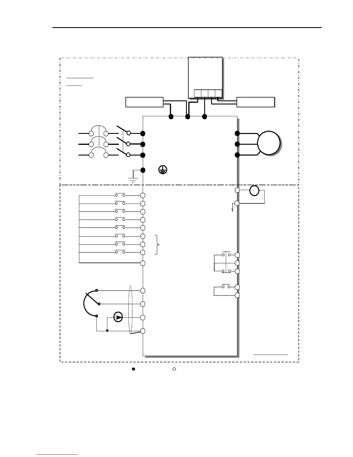
speed signal:
+ 12V, 10mA
Speed signal input:
0 ~ 10V
Speed signal input:
4 ~20mA (250ohm)
Common for
VR, V1, I
Fault output relay
less than AC250V, 1A
less than DC30V, 1A
Multi-function output relay1
less than AC250V, 1A
less than DC30V, 1A
Factory setting: ‘Run’
Note) Main Circuit Terminals Control Circuit Terminals.
1. The terminal configuration varies depend on the model number. Please refer to the ‘1.7 Power terminals’.
2. Analog output voltage is adjustable up to 12V.
3. Analog speed command may be set by Voltage, Current or both.
4. The Common Busbar between P1/L1 and P2/L2 must be removed befor e installing DC Reactor.
5. 1 ~ 10 HP inverters have built-in br aking circuit. Braking resistors are only i ncluded for 1 ~ 5HP i nverters.
15~30HP inverters have built-i n DB unit. 15 ~ 100 HP inverters need optional braking unit and resistor.
6. In case of 40 HP or more than,the terminal is CM terminal which has same electric potential with Common Terminal.
P2/
L2
1
P1/
L1
1
DC Bus Choke (Optional)