Electrical Characteristics
www.lsi.com/channel/products 23
Chapter 3.
Specifications
Electrical Characteristics
The following subsections provide the power supply requirements
for the 9750 family of SATA+SAS RAID Controller Cards.
“Power Supply Requirements for the 9750-4i, 9750-8i, 9750-
4i4e, and 9750-8e Controller Cards”
“Power Supply Requirements for the 9750-24i4e and 9750-
16i4e Controller Cards”
Power Supply Requirements for the 9750-4i,
9750-8i, 9750-4i4e, and 9750-8e Controller Cards
All power is supplied to the controller through the PCI Express
3.3
V rails and the 12 V rail. Onboard switching regulator circuitry
operating from the 3.3 V rails and the 12 V rail provide the
necessary voltages. The following states determine the typical
current consumption of the 9750 controller card:
State 1: During a hard reset
State 2: During a stress test
State 3: While sitting idle at the prompt
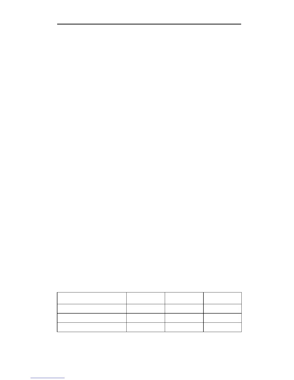
The supply voltages are 12 V ± 8 percent (from PCI edge connector
only) and 3.3 V ± 9 percent (from PCI edge connector only).
Table 3 lists the power supplies for the controller for each of the
three states at the different voltages.
Table 3: Power Supplies for the 9750-4i, 9750-8i,
9750-4i4e, and 9750-8e Controller Cards
PCI Edge Connector State 1 State 2 State 3
3.3 V supply 0.330 A 0.330 A 0.330 A
12 V supply 1.000 A 1.810 A 1.530 A
3.3 V auxiliary supply 0.030 A 0.030 A 0.030 A
 Loading...