12
12
The GS820 System
The GS820 System
2. For GS011 angle/length sensors only: Carefully
remove the cover of the GS101 cable reel.
3. Loosen the mounting screw in the slotted hole
of the angle sensor mounting plate.
4. Pivot the angle sensor slightly until angle
indication is correct. Repeat the angle validation
(step 1) as required.
2.3c Angle Calibration Procedure
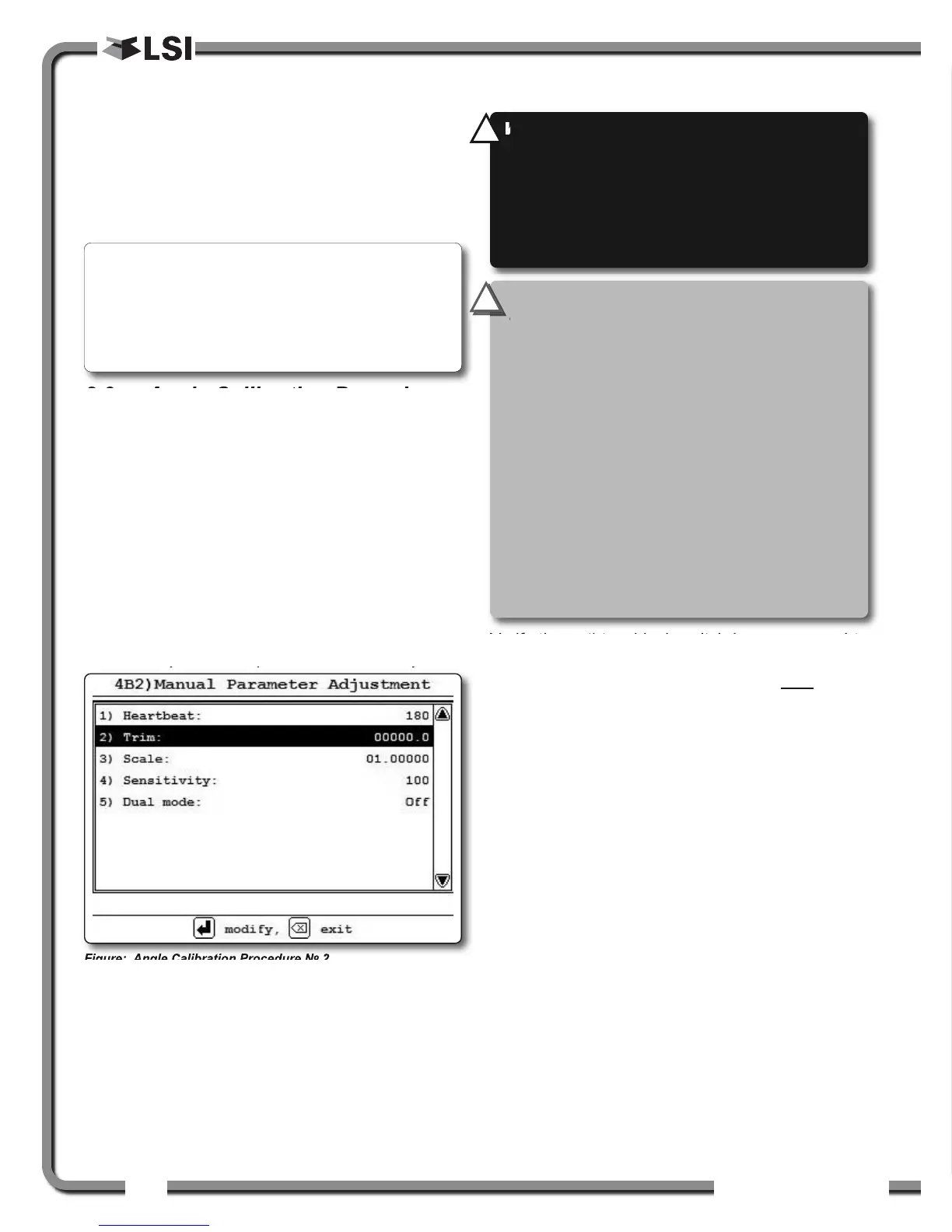
№ 2: Correct with the GS820
Calibrate angle indication by adjusting the trim (offset)
value in the GS820 display; the GS820 will then
communicate the updated trim value to the sensor.
1. Position the boom at a precisely known angle.
2. Go to menu 4) and select 4B) S
ENSOR CALIBRATION.
3. Enter the user password and press Enter.
4. Select 4B2) M
ANUAL PARAMETER ADJUSTMENT.
5. Use Up and Down to select the angle sensor
to be calibrated and press Enter.
6. Select 2) T
RIM: and press Enter to modify.
7. Use Up and Down to modify the trim value.
Example: If angle indicated is 0.3° over the actual
angle, adjust the trim value to -0.3.
Example: If angle indicated is 0.9° below the actual
angle, adjust the trim value to 0.9.
8. Press Enter to save changes.
9. Press Exit to return to the operation display.
10.Verify accurate angle indication at both very
high and very low angles.
2.4
2.4
Anti-Two-Block Switch
Anti-Two-Block Switch
Verify the anti-two-block switch is programmed to
the GS820 display. Switches shipped with displays
are pre-programmed in the factory. Test
: if the
switch has been programmed to the display then
the display will go in to two-block alarm when the
wire rope of the switch is released. Press Bypass
to silence the alarm until the next two-block event
or simulation. If the switch has not been
programmed to the display, this should be done
before proceeding with installation. See the section
How to Add a Sensor to the GS820.
2.4a GS050 Installation
1. Position the sensor mounting bracket. To
ensure that the sensor can pivot securely on the
mounting bracket throughout the full range of
boom angle, the mounting bracket must be
positioned at a 30° from horizontal with the
boom parallel to the ground and such that the
locking pin of the mounting bracket points up.
Bolt or weld securely.
Figure: Angle Calibration Procedure № 2
Note: When the angle sensor is moved very slowly,
it may take several seconds to see an update at the
GS820 display. Instead move the sensor up a couple
of degrees, and then bring it back down to where it
should be. The small light on the angle sensor
flashes when it transmits a new value to the display.
WARNING!
Keep the anti-two-block switch
away from the boom and any connecting
metal structures when welding mounting
brackets to the boom. Proximity to welding
may cause permanent damage to the anti-
two-block switch and render the anti-two-
block system unsafe.
!
!
IMPORTANT!
To ensure reliable radio
communication between the anti-two-block
switch and the GS820 display the following
conditions must be respected:
• The antenna of the anti-two-block switch
should not be in contact with metal.
• The anti-two-block switch antenna should
point to the left or to the right of the boom;
it should not point directly to, or away from,
the GS820 display.
• The anti-two-block switch antenna should
have a clear line of sight to the GS820
display; in most cases this means mounting
the sensor on the same side of the boom as
the operator's cab.
!
!