ISTALLATIO
ISTALLATIO
19
19
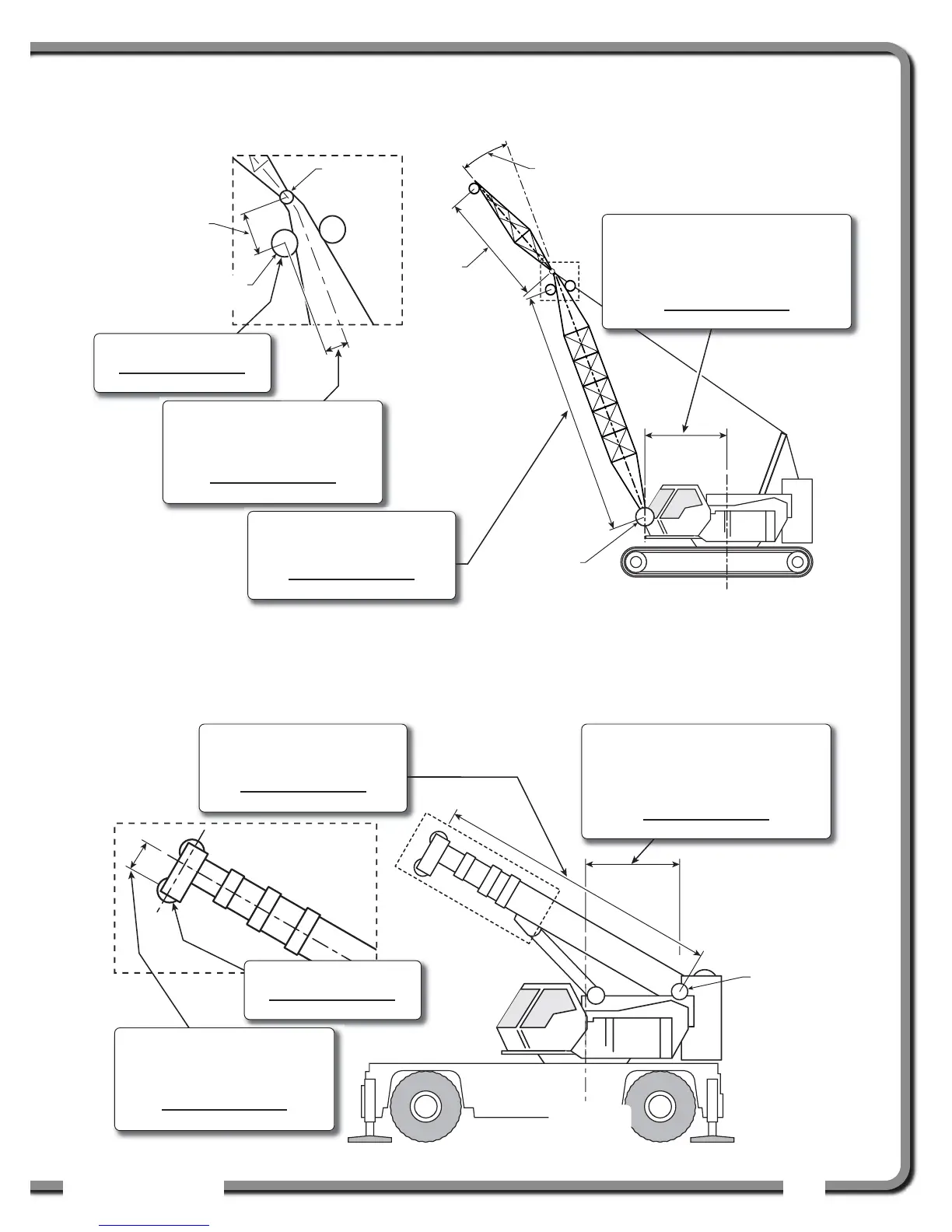
2.6c Basic Radius Parameters for a
Lattice Crane
2.6d Basic Radius Parameters for a
Telescopic Boom Crane
Crane center
of rotation
Boom
base pin
Jib mounting
point
Jib offset
angle
Jib
length
Head
sheave
Sheave head
length parallel
Menu 4C) 12E) SHEAVE HEAD LENGTH
PERPENDICULAR
The distance from the head sheave
centre to the boom centerline.
(Your measurement)
Menu 4C) 1) BOOM LENGTH
The distance from the boom base
pin to the head sheave centre.
(Your measurement)
Menu 4C) 12G) SHEAVE RADIUS
(Your measurement)
Menu 4C) 2) SLEW OFFSET
The distance from the boom base pin to
the crane centre of rotation.
If the boom base pin is behind the centre
of rotation this value will be negative.
(Your measurement)
Boom
base pin
Menu 4C) 12E) SHEAVE HEAD LENGTH
PERPENDICULAR
The distance from the head sheave
centre to the boom centerline.
(Your measurement)
Menu 4C) 1) BOOM LENGTH
The distance from the boom base
pin to the head sheave centre.
(Your measurement)
Menu 4C) 12G) SHEAVE RADIUS
(Your measurement)
Menu 4C) 2) SLEW OFFSET
The distance from the boom base pin to
the crane centre of rotation.
If the boom base pin is behind the centre
of rotation this value will be negative.
(Your measurement)
Crane center
of rotation
Figure: Basic radius parameters for a lattice crane. Typical installation. Not to scale.
Figure: Basic radius parameters for a telescopic boom crane. Typical installation. Not to scale.