ISTALLATIO
ISTALLATIO
15
15
2.5
2.5
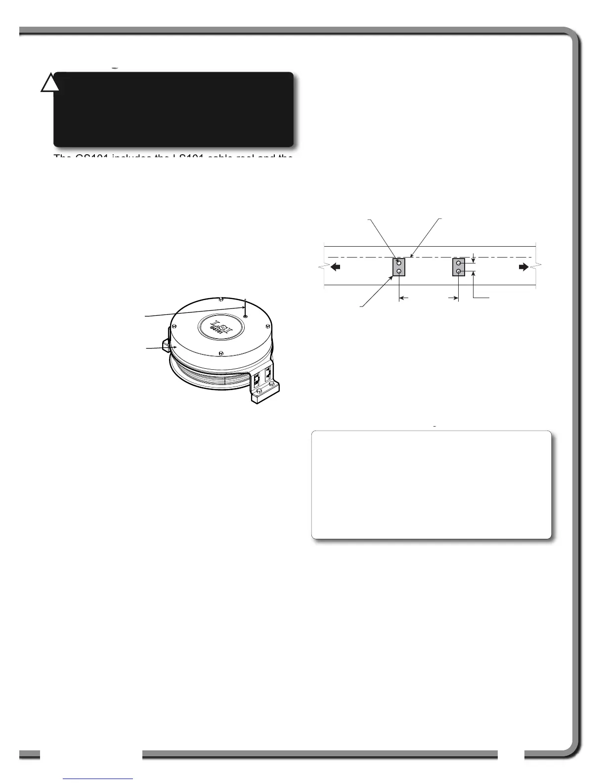
Length Sensor Cable Reel
Length Sensor Cable Reel
The GS101 includes the LS101 cable reel and the
GS011 angle/length sensor. The GS011 is
concealed under the cover of the LS101, though
the antenna is visible. Following cable reel
installation and boom length indication calibration,
boom angle indication will have to be verified and
possibly calibrated. Refer to Angle Calibration
Procedure № 1: Mechanical Set-Up and Angle
Calibration Procedure № 2: Correct with the
GS820, sections of this manual.
2.5a Maximum Boom Extension
Confirm the maximum extension of the LS101 cable
reel is compatible with the maximum boom length.
Step 1. Note the cable reel maximum extension: 100 feet
(30.5 metres) unless specified otherwise.
T = ____________________
Step 2. Note the retracted boom length.
A = ____________________
Step 3. Note the maximum extended boom length, not
including jib.
B = ____________________
Step 4. Calculate maximum boom extension.
C = B – A =____________________
Step 5. Compare cable reel maximum extension (T) to
maximum boom extension (C).
D = T – C =____________________
Maximum cable reel extension must be greater
than maximum boom extension.
2.5b Mounting the Cable Reel
1. Determine placement. Find a clear mounting
position on the left side of the first (main) section
of the boom. The mounting position should be
close to the base of the boom; at least ten feet
(three metres) from the tip of the first section and
where the cable reel won’t obstruct free boom
movement at all boom angles and slew positions.
Furthermore, the reel must be placed such that
the cable has a clear straight line to the end of
the last section at all boom lengths.
2. Mount the welding tabs. They must be placed
parallel to each other, with 16 1/8” inches
between the holes’ centres. Install the tabs such
that they create a level mounting position in line
with the boom at 0 degrees.
3. Attach the reel to the welding tabs with the bolts
provided.
4. Install the first cable guide (PA111) about 10 feet
(3 metres) from the cable reel. Correct alignment
of the first guide is critical to ensure orderly
winding of the cable on the reel. Install the other
guides at the end of each of the intermediate
sections and the anchor (PA113) at the end of the
last section. All guides must be aligned so as to
permit unobstructed movement of the cable.
5. Pull out at least 5 feet (1-1/2 metres) of cable,
but not more than half the excess extension of
measurement D. Feed through the cable guides
16 1/8 in. apart,
2 1/4 in. apart,
Figure: Cable reel mounting position
WARNING!
Arc welding may damage
LSI
LSI
sensors, causing immediate failure or greatly
reducing functional life. Arc welding on or near
LSI
LSI equipment will void warranty. Keep
LSI
LSI
equipment well clear of any arc welding.
!
!
Note: When factory installed the GS011
angle/length sensor transmitter is integrated to the
LS101 cable reel with the angle sensor zeroed. If
the cable reel is installed perfectly level on the
boom at 0 degrees, the angle sensor of the GS011
will also be zeroed. Minor adjustments to the angle
sensor (within plus or minus two degrees) are
possible after cable reel installation.

 Loading...
