22
22
The GS820 System
The GS820 System
2.8
2.8
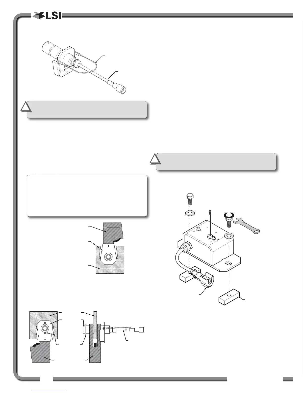
Wireless Load Pins
Wireless Load Pins
2.8a LP011, LP015, and LP026
1. Mount the load pin to the boom tip or block by
replacing the pin of the wedge socket. The load
pin is directional and must be oriented correctly
to indicate load accurately. Install the pin so that
the bracket embraces the wedge socket and
prevents pin rotation.
2. Secure the load pin in place with a cotter pin or
other suitable keeper device.
2.8b Load Pin Transmitter GS001
1. Determine the transmitter mounting position.
a. The load pin and transmitter pigtails must
connect easily without stretching or
kinking at all boom angles and working
conditions. The jumper cable may be
used between the load pin and
transmitter to increase transmitter
placement options.
b. There must be direct unobstructed line of
sight from the transmitter to the display;
this may not be required on cranes with a
maximum boom length less than 100 feet
(33 metres).
c. The transmitter antenna must not be in
contact with any metal object.
2. Weld the mounting blocks where required.
3. Mount the load pin transmitter on the mounting
blocks.
Figure: Install the load pin transmitter GS001
IMPORTANT!
Do not pull on a load pin
by the pigtail, pull on the handle wire.
!
!
IMPORTANT!
Do not weld in proximity to
LSI
LSI sensor/transmitters.
!
!
Note: When installed at the boom tip the lot
number can be read right side up and the “line
pull” arrow points down towards the block. When
installed at the hook ball or block, the lot number
can be read upside down and the “line pull” arrow
points up towards the boom tip.
 Loading...

