Page
5
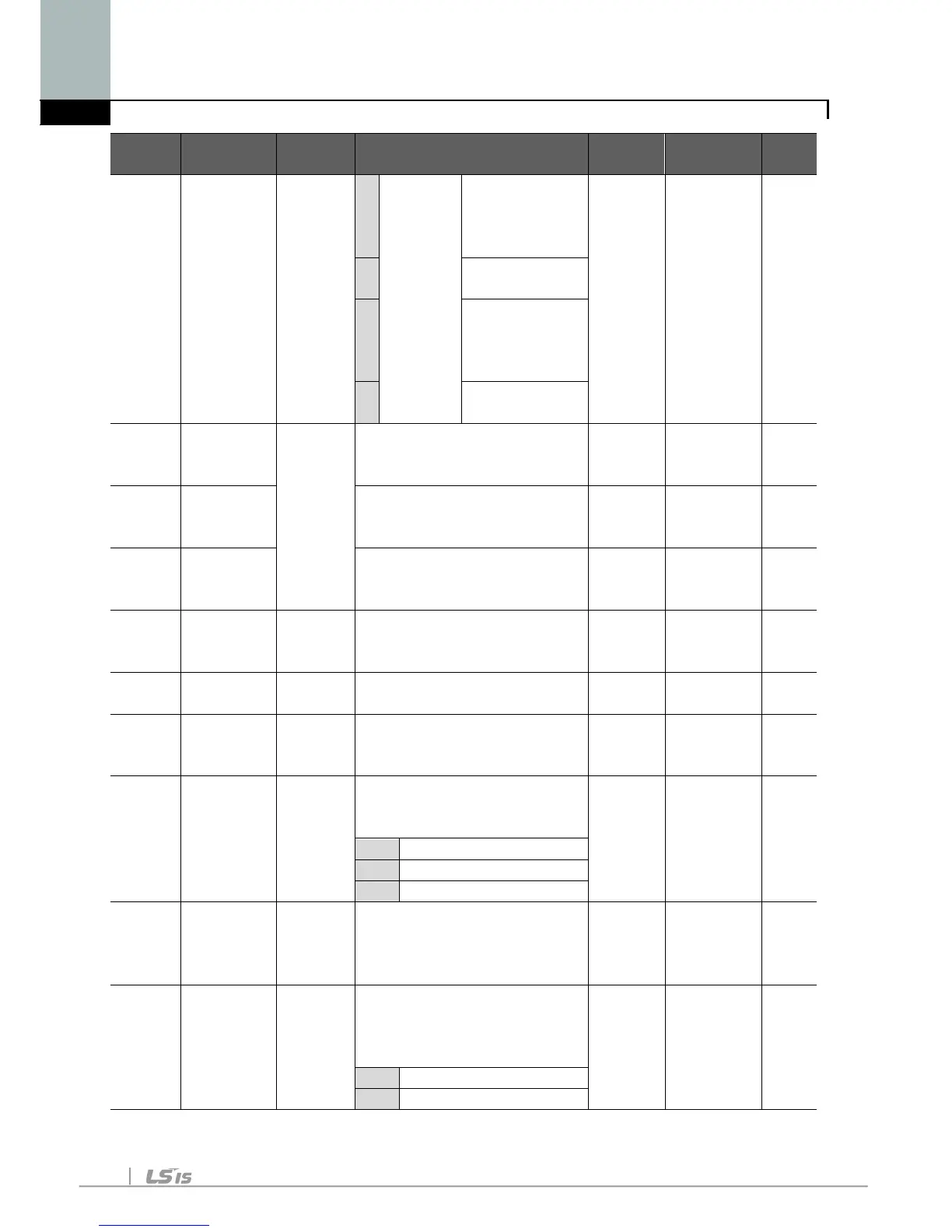
Setting via
potentiometer
on the keypad
7
Setting via
potentiometer
on the keypad
8
Modbus-RTU
Communication
St1 [Multi-Step
frequency
0/400
[Hz]
This parameter sets Multi-
Step frequency 1 during
10.0 O
St2 [Multi-Step
frequency
This parameter sets Multi-
Step frequency 2 during
20.0 O
St3 [Multi-Step
frequency
This parameter sets Multi-
Step frequency 3 during
30.0 O
CUr [Output
current] -
This parameter displays
the output current to the
-
This parameter displays
- -
dCL [Inverter
DC link
-
This parameter displays
DC link voltage inside the
- -
vOL [User
display
select]
-
This parameter displays
the item selected at H73-
[Monitoring item select].
tOr Torque
nOn [Fault
Display]
-
This parameter displays
the types of faults, frequency
and operating status at the
rotation
select]
F/r This parameter sets the
direction of motor rotation
when drv - [Drive mode] is