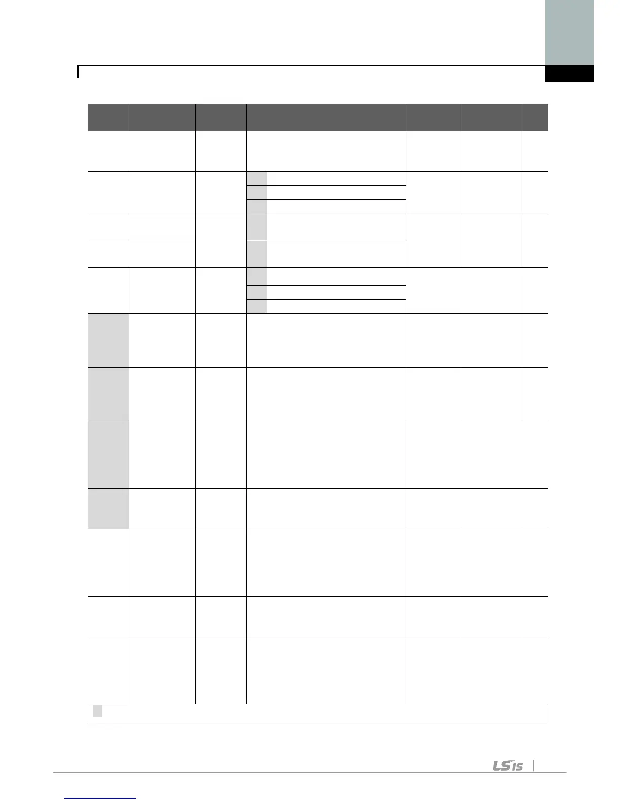
F 0 [Jump
code]
0/60 This parameter sets the
parameter code number to
1 O
F 1
[Forward/
Reverse
run disable]
0/2
2 Reverse run disable
F 2 [Accel
0/1
0
Linear 0 X
F 3 [Decel
pattern]
1
S-curve
F 4 [Stop mode
select]
0/2
0
Decelerate to stop 0 X
F 8
1)
[DC Brake
start
frequency]
0/60
[Hz]
This parameter sets DC
brake start frequency.
It cannot be set below F23 -
5.0 X
F 9 [DC Brake
wait time]
0/60
[sec]
When DC brake frequency
is reached, the inverter holds
the output for the setting time
before starting DC brake.
0.1 X
F10 [DC Brake
voltage]
0/200
[%]
This parameter sets the
amount of DC voltage applied
to a motor.
It is set in percent of H33 –
50 X
F11 [DC Brake
time]
0/60
[sec]
This parameter sets the time
taken to apply DC current to a
motor while motor is at a stop.
1.0 X
F12 [DC Brake
start
voltage]
0/200
[%]
This parameter sets the
amount of DC voltage before a
motor starts to run.
It is set in percent of H33 –
50 X
F13 [DC Brake
start time]
0/60
[sec]
DC voltage is applied to the
motor for DC Brake start time
before motor accelerates.
0 X
F14 [Time for
magnetizing
a motor]
0/60
[sec]
This parameter applies the
current to a motor for the set
time before motor accelerates
during Sensorless vector
1.0 X
1) : Set F4 to 1 (Stop via DC brake ) to view this function
 Loading...

