9.3 Structure of Frame
9.3.1 Structure of frame in the ASCII mode
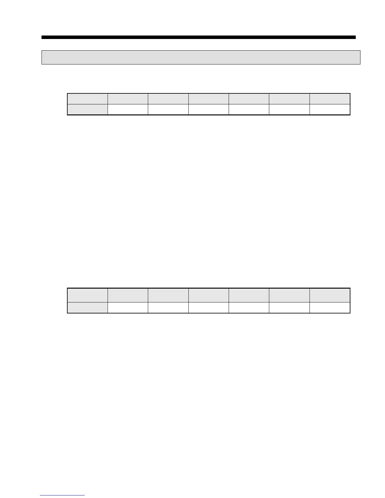
Frame structure in the ASCII mode is as follows.
Classification Start Station no. Function code Data Error check End
Size (byte) 1 2 2 N 2 2
(1) Characteristic of ASCII mode
(a) In the ASCII mode, start of frame is indicated with colon (:), which is ASCII code, and end of frame is
indicated with ‘CRLF’.
(b) Each character allows maximum 1s interval.
(c) How to check the error uses LRC, it takes 2’s complement except frame of start and end and converts it
as ASCII conversion.
(2) Address area
(a) It consists of 2 byte.
(b) When using the XGT Cnet I/F module, range of station is 0~31.
(c) Station number 0 is used for client.
(d) When server responds, it contains self address to response frame to know client’s response.
(3) Data area
(a) Transmits the data by using the ASCII data, data structure changes according to function code.
(b) In case of receiving normal frame, it responds as normal response.
(c) In case of receiving abnormal frame, it responds by using error code.
(4) Error check area
How to check error of frame takes 2’s complement except start and end of frame and converts it as ASCII.
9.3.2 Frame structure in the RTU mode
Frame structure in the RTU mode is as follows.
Classification Start
Function code Data Error check End
size(byte) Idle time 1 1 N 2 Idle time
(1) Characteristic of RTU mode
(a) It uses hexadecimal.
(b) Start character is station number and frame is classified by CRC error check.
(c) Start and end of frame is classified by adding idle time of 1 bit.
(d) Between frames, there is interval of 3.5 character time. When exceeding 1.5 character time, it is
acknowledged as independent frame.
(2) Address area
(a) It consists of 1 byte.
(b) When using the XGT Cnet I/F module, range of station is 0~31.
(c) Station number 0 is used for client.
(d) When server responds, it contains self address to response frame to know client’s response.
(3) Data area
(a) Transmits the data by using the Hex. data, data structure changes according to function code.
(b) In case of receiving normal frame, it responds as normal response.
(c) In case of receiving abnormal frame, it responds by using error code.
 Loading...