9.4.2 Read Input Status (02)
(1) Reading bit of input area
In case of reading data of bit type of input area, request and response frame is as follows.
Tail of frame is applied in case of ASCII mode.
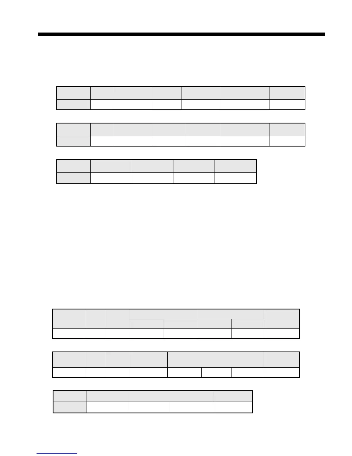
(a) Request frame
Classification
Tail (CRLF)
Size (byte) 1 1 1 2
(2) Details of frame
(a) Station no.: indicates station no. of slave to read bit of input area
(b) Function code: ‘02’ indicating Read Input Status
(c) Address: indicating start address of data to read. It consists of 2 byte. At this time, start address conforms
to modbus address regulation.
(d) Data size: size of data to read, consists of 2 byte
(e) Frame error check: in case of ASCII mode, it uses LRC and in case of STU mode, it uses CRC for error
check. It consists of 2 byte.
(f) Tail: it is applied in case of ASCII mode, CRLF is added after LRC.
(g) No. of byte: no. of byte of data responding
(h) Data: address of request frame is start address and transmits data with byte unit.
(i) Error code: Error code is expressed by adding 80(Hex) and in case of reading bit of output area, it is
expressed 82(Hex).
(j) Exceptional code: details of error, consists of 1 byte.
(3) Frame example
Example that reads bit (20~38) from station number 1 server acting as modbus RTU
(a) Request frame
Classificatio
n
Statio
n no.
Function
code
Address Data size
Error check
Upper byte Lower byte Upper byte Lower byte
Frame 01 02 00 13 00 13 CRC
(b) Response frame (When receiving normal frame)
Classificatio
n
Statio
n no.
Function
code
No. of byte Data Error check
Frame 01 02 03 12 31 05 CRC
(c) Response frame (When receiving abnormal frame)
Classification Station no. Function code Exceptional code Error check
Frame 1 82 2 CRC
 Loading...