9.4.7 Force Multiple Coils (0F)
(1) Writing continuous bit to output area
In case of writing continuous bit to output area, request and response frame is as follows.
Tail of frame is applied in case of ASCII mode.
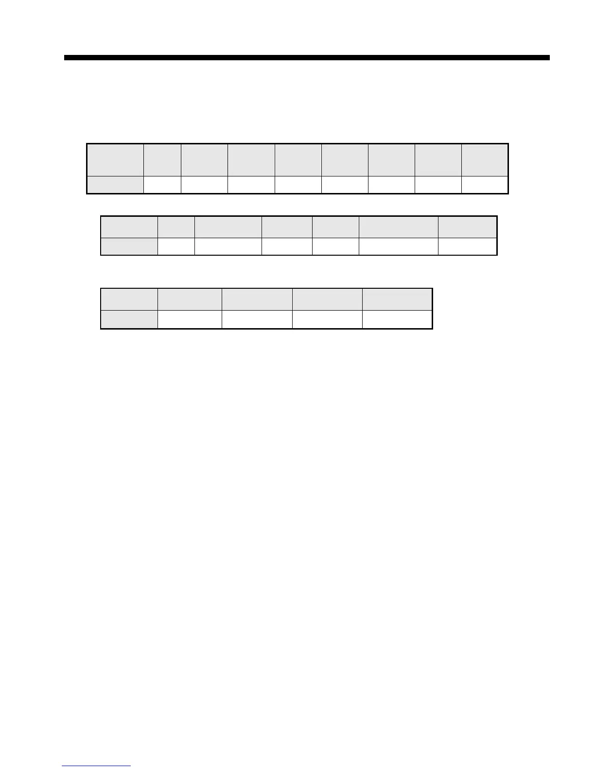
(a) Request frame
Classification
Station
no.
Function
code (0F)
Address
No. of
output
Data size
Frame error check Tail (CRLF)
Size (byte) 1 1 2 2 2 2
(c) In case of response frame (In case of receiving abnormal frame)
Classification Station no. Error code
Tail (CRLF)
Size (byte) 1 1 1 2
(2) Details of frame
(a) Station no.: indicates the station no. of slave to write continuous bit of output area.
(b) Function code: ‘06’ indicating Force Multiple Coils
(c) Address: start address of data to read and it consists of 2 byte. At this time, start address conforms to
Modbus address regulation.
(d) No. of output: no. of output to write and it consists of 2 byte
Ex.) When writing 10 continuous data from address number 20, no. of output is 000A(Hex)
(e) Data size: indicates no. of output as byte. Namely, in case data size is 1, no. of data is 9.
Ex.) In case of writing 10 continuous bits, data size is 2.
(f) Output: data value to write in the address set in the Address.
(g) Frame error check: in case of ASCII mode, it uses LRC and in case of STU mode, it uses CRC. It
consists of 2 byte.
(h) Tail: it is applies in case of ASCII mode, CRLF is added after LRC.
(i) No. of byte: no. of byte of response data
(j) Error code: error code is expressed by adding 80(Hex) to function code and in case of writing continuous
bit of output area, it is expressed as 8F(Hex).
(k) Exceptional code: indicates detail of error and consists of 1 byte.
 Loading...