Instruction Manual
______________________________________________________________________
_____________________________________________________________________________
BE6043-16 Stand Alone Multipoint System LumaSense Technologies A/S
Page 14 of 25
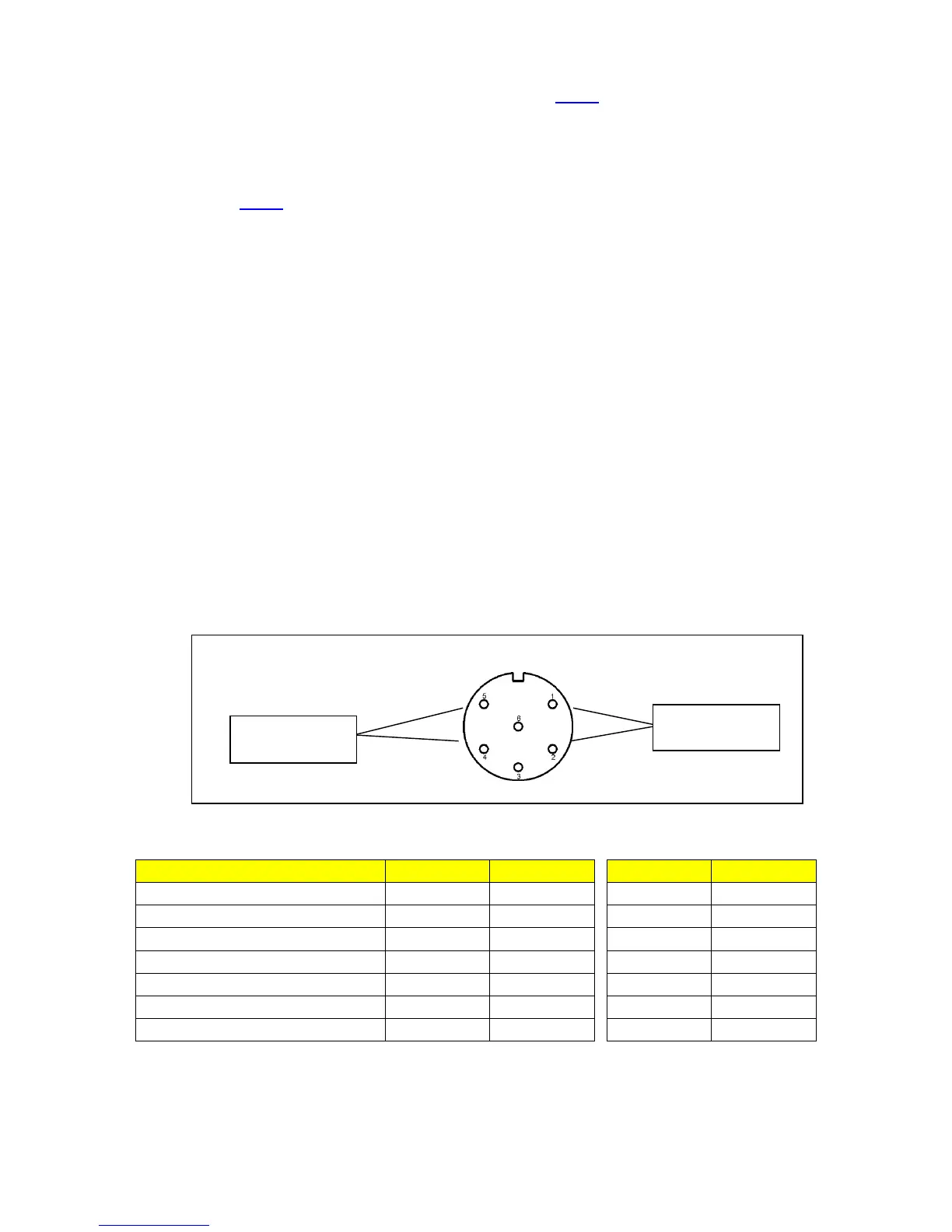
Pin 4 and 5 are normally open, see Fig.4
Whenever one or more gases exceed the corresponding high alarm
limit 2, the Monitor breaks the electrical connection between pins 4
& 6 and make electrical connection between pins 4 and 5. See
Fig.5
The alarm relay is furthermore activated during the following
conditions:
• Power off.
• If a measurement task is not running.
• During calibration.
LumaSense supplies a 6-pin DIN plug (male) with a locking collar
JP0600 for connecting external alarm devices to the alarm relay.
Caution:
The DC voltage across the relay contacts must not exceed 25V. The
potential on the relay contacts must not be more than 25VDC above
chassis potential, as this will cause an excessive leakage current. The
current through the contacts must not exceed 100mA. AC voltages
must not be connected to the Alarm Relay socket.
Fig.4 Configuration of the pins in the alarm relay socket
Figure 5 Function of the alarm relays
 Loading...