Instruction Manual
________________________________________________________________________
_____________________________________________________________________________
BE6043-16 Stand Alone Multipoint System LumaSense Technologies A/S
Page 6 of 25
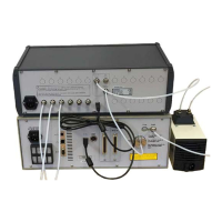
Figure 2. Tube connection with: Dust filter DS2306, UD5023 and Genie
Membrane Separator UA1365.
3.0 Set-up from the Gas Monitor Front Panel
3.1. Introduction
The set-up from the front panel is schematically described in the Quick
Set-up Guide see Figure 3.
The Gas-Monitor Set-up branch and all functions available in this part of the Set-
up Guide is described in details in the Gas Monitor Instruction Manual
(BE6030 for Type 1314i, BE6025 for Type 1412i , BE6028 for Type
3434i and BE6049 for Type 1512) supplied with the Gas Monitor. Please
consult the Gas Monitor User manual for further description and
guidance in the use of the Gas Monitor Set-up, start and stop
measurements, store data in Memories etc. The Gas Monitor User
Manual also gives an in depth description of all front panel keys. It is
recommended to get familiar with these keys and set-up menu in the
Gas Monitor branch using the Gas Monitor manual before starting
setting up a Stand Alone Multipoint System.
The Analog/Relay branch is only available for Type 1314i and 1512 with an
Analog/Relay Module UA1373 for 1314i and UA1374 for 1512 installed
in the Monitor from the factory. If a UA1373 (1314i) or UA1374 (1512)
Module is not installed this branch will not be visible in the Set-up Menu
on the Gas Monitor.
The Multipoint Sampler branch becomes available in the Gas Monitor’s set-up
menu when a Type 1409 is connected to the Gas Monitor via the USB
Host interface.
 Loading...