Instruction Manual
______________________________________________________________________
_____________________________________________________________________________
BE6043-16 Stand Alone Multipoint System LumaSense Technologies A/S
Page 15 of 25
4.4.3. Alarm limits for 1314 with the Analog/Relay Module UA1373 and
for 1512 with Analog/Relay Module UA1374
The Analog/Relay Module UA1373/UA1374 is installed in the Gas
Monitor from the factory.
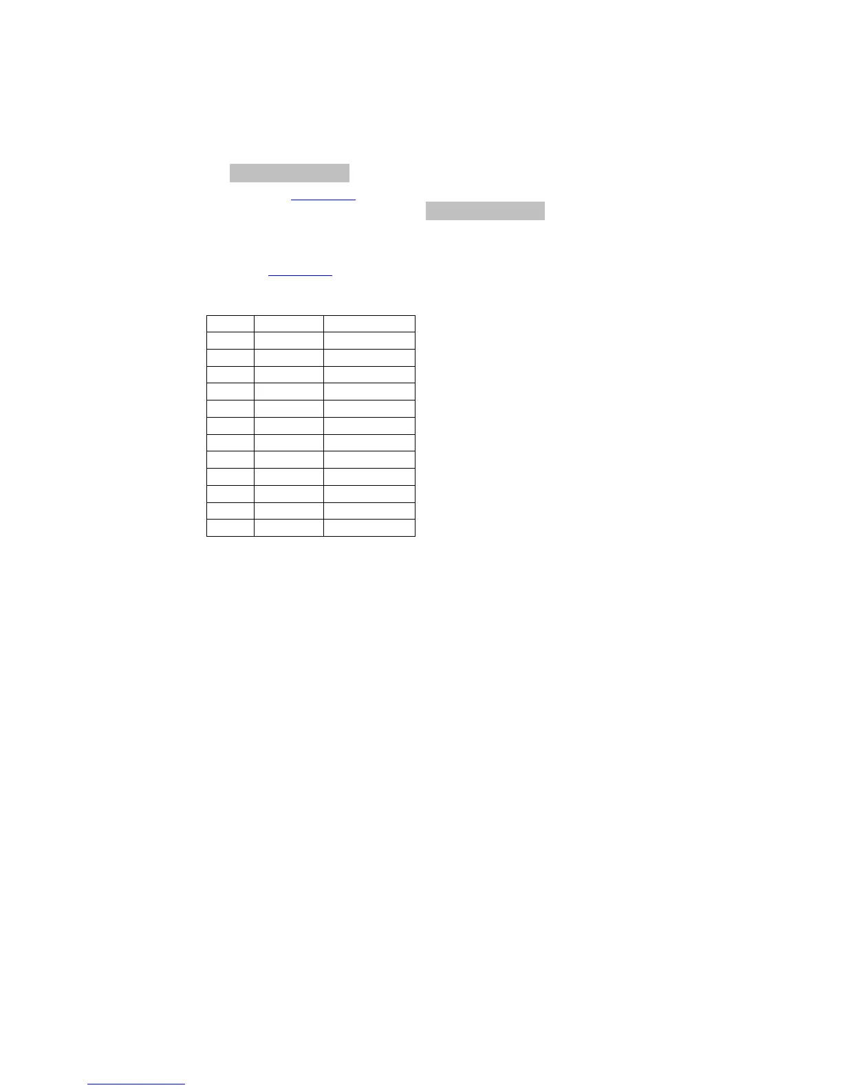
The Analog/Relay Branch will now appear in the Set-up structure
as shown in Figure 3.
Following the set-up guide in Analog/Relay Output Mode there are
two possibilities.
Gas Mode : the behaviour of the relays will be according to the one
shown in Figure 6 below.
Figure 6 Gas Mode Alarm Relay Settings
Channel Mode: In this part of the set-up structure, it is possible to
select the Alarm setting (Alarm limit 1 or 2) for each Multipoint
Sampler Channel and combine with appropriate Relay or select
“none” not to have a relay activated at that Channel.
5.0 Setting up the Analog/Relay interface module
When the UA1373 is installed in the 1314i or the UA1374 is installed
in the 1512, the following additions will be available in the Set-up
menu: Units for analog output, analog output scaling and selection of
Relay output mode and limits for Relay output.
Before the UA1373/UA1374 can be used, the Analog output units,
Analog concentration limits and the relay output limits parameters
must be entered.
Please note that these set-up menus only are available, when the
UA1373/UA1374 is installed in the instrument.
The set-up of the Analog/Relay interface Module can be performed
either from the Front Panel of the Gas Monitor or by using the
BZ7007 Remote and Offline SW. Please consult the BZ7007 User
 Loading...