Instruction Manual
________________________________________________________________________
_____________________________________________________________________________
BE6043-16 Stand Alone Multipoint System LumaSense Technologies A/S
Page 5 of 25
To prevent dust from entering the tubing and instruments it is
recommended to use external filters at the sampling points. LumaSense
have the following filter options DS2306 or UD5023 (see Figure 2).
WARNING! Avoid water condensation in the instrument.
Liquids must be prevented from entering the instrument. It is therefore
important that warm humid gases are not drawn into a cold instrument
because condensation will take place. If such a situation is likely to
occur, you must ensure that the gases are drawn through water-trap
filters before they enter the sampler channels of the 1409. The In-line
Genie Membrane Separator (LumaSense order no. UA1365 see Figure
2) avoids condensation in the measuring instruments. For further
information please consult BE6037 supplied with the Type 1409.
• to the Gas Monitor being used to analyse the gases that are sampled;
This connection uses the same tubing (PTFE, LumaSense No. AF0614)
as for the sampling tubes. The tubing is connected to the Outlet to
Analyzer stub on the rear panel of the 1409, and to the Air Inlet stub
on the rear panel of the Gas Monitor (see Figure 1).
For further information, please consult BE6037 supplied with the Type
1409.
• to the external pump (optional).
The Waste Air Outlet stub, next to the Outlet to Analyzer stub, on
the rear panel of the 1409, connects the external pump (optional) to the
1409’s sampler system see Figure 1. If you do not wish the waste air
from the pump to mix with the air in the room where the 1409 is
positioned, connect a length of PTFE tubing (LumaSense no. AF0614) to
the waste air outlet stub on the external pump and direct the tubing to a
suitable exhaust-point.
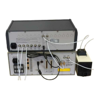
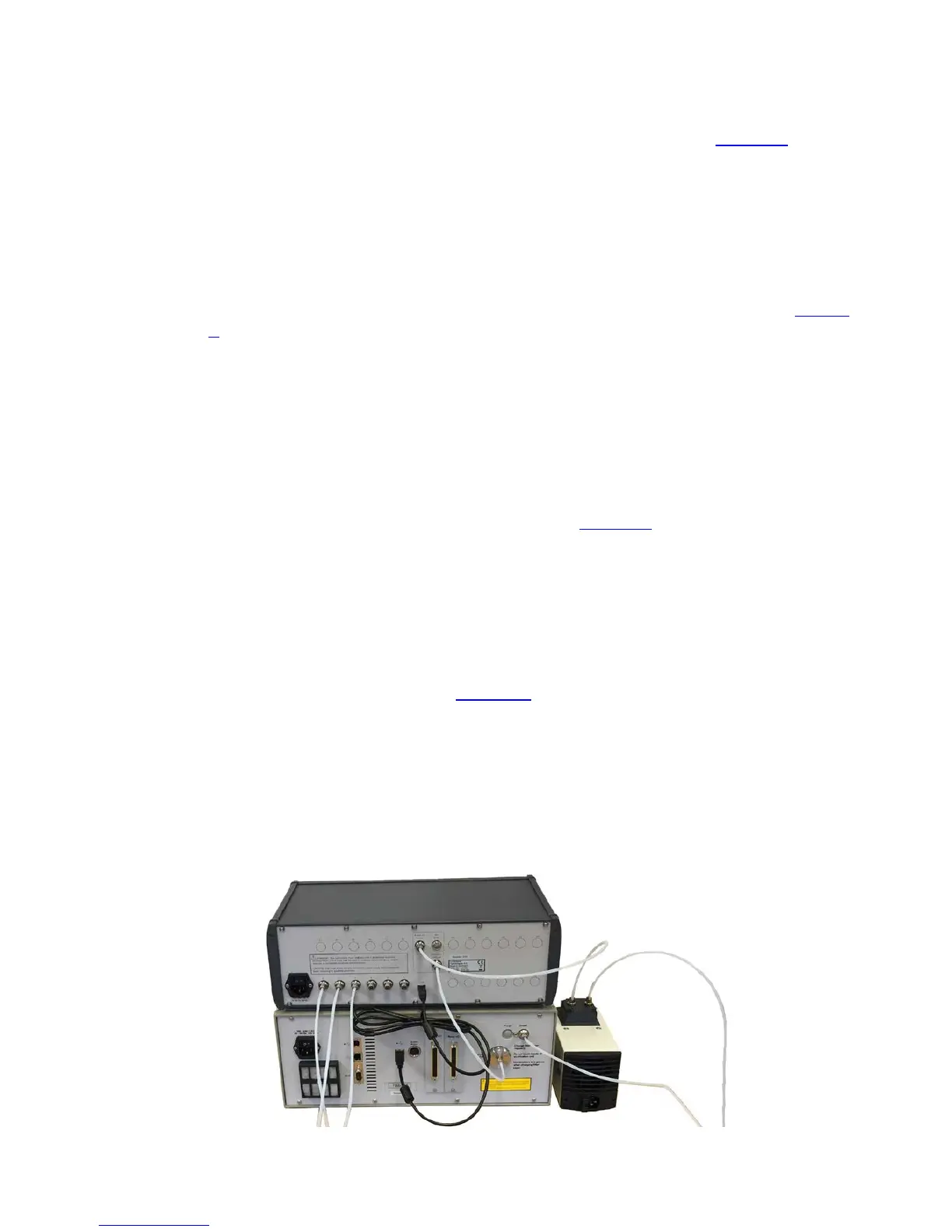
Figure 1. Tube and Cable connection with connection to an external
pump.
 Loading...