50
2. Depending on the size of the workpiece, move the sliding rail
into the ideal position relative to the main table, then tighten
both sets of wingnuts.
Figure 17
Figure 19
(a)
(b)
(c)
(2)
Figure 18
8
11
(9)
(1)
(5)
(3)
(4)
(7)
(6)
(8)
(a)
(b)
Figure 21
Figure 22
Speed Chart
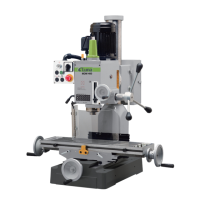
4.7.11 Installing the Workpiece Clamp
Safe workpiece guidance is a precondition for accurate and safe
working. It is therefore important that you use the workpiece
correctly.
1. Fit the pulling rod into its locating hole situated on the stop
tube (see Figure 18). Hold the rod in place with the supplied
counter sunk screw (from below).
2. Attach the workpiece clamp (12) to the pulling rod; the desi-
red height can be held with the handwheel.
3. Place the workpiece on the bench.
4. Apply the workpiece clamp with the lever in position(a) to the
pulling rod.
3. Loosen the height adjusting handwheel and place the lever in
position (b), lower the clamp until it is touching the workpie-
ce, re-tighten the handwheel to secure.
4. To clamp the workpiece, move the clamp into position(c).
4.8 Installing Mobile Wheel Kit (optional)
1. Place “U” Shape Bracket(1) onto Front Wheel Kit Ass’y(2).
2. Insert Hex Head Screw M10x70(3), secure Front Wheel Kit
and Sleeve(4) to work stand.
3. Insert Special Thread(5) and secure Front wheel kit.
4. Secure Rear Castor Frame(7) to workstand with two Hex Head
Screw M10x20 & washer.
5. When move the machine adjust the Allen Bolt M12x50,and
raise the machine about 5mm above floor. Insert the Rear
Castor Ass’y, push the lever down and pull the machine round
the workshop.
5. ADJUSTMENT & OPERATION
CAUTION!
Read the manual before assembly and operation.
Become familiar with the machine and its operation before
beginning any work. Serious personal injury may result if safe-
ty or operational information is not understood or followed.
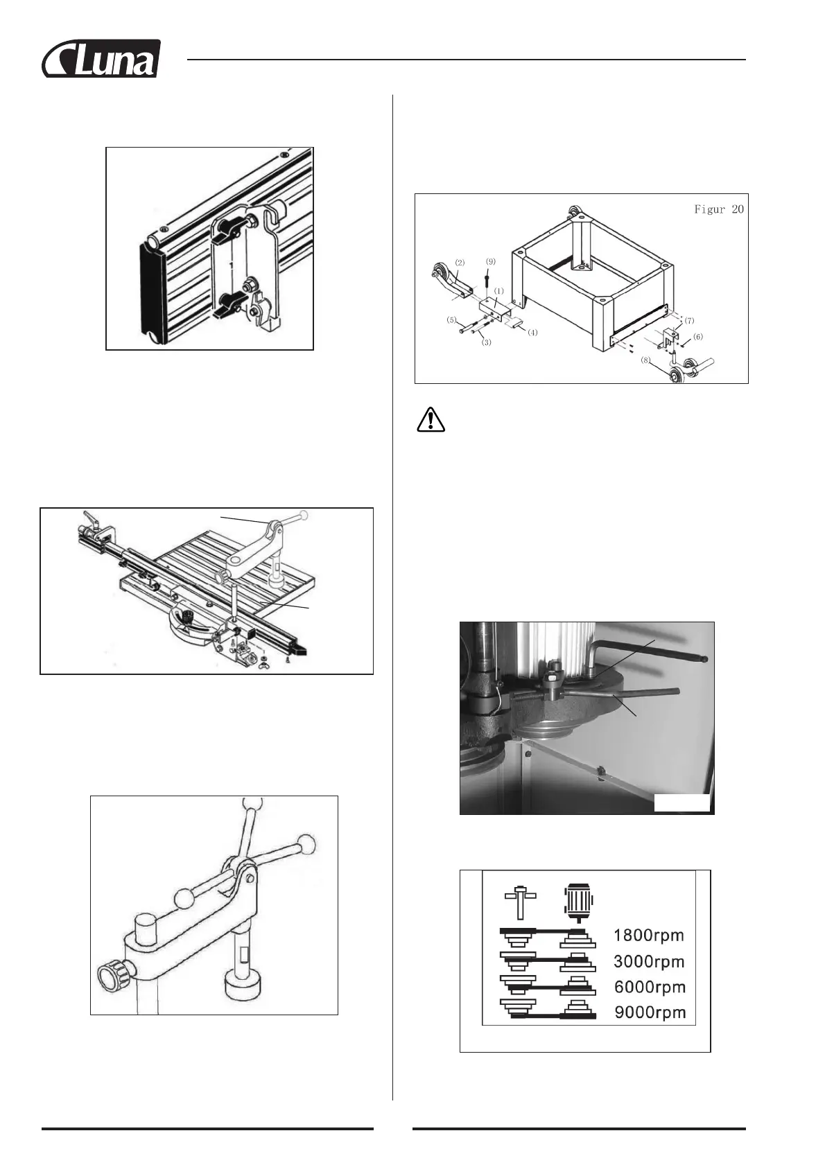
5.1 Speed Changes
This machine is equipped with a V-belt drive system that controls
the speeds. To change spindle speeds:
1. Unplug the machine.
2. Loosen the two Startype Screw M6x30, open the Machine
Housing Door.
3. Loosen the Allen Bolt M12x40(a) with allen wrench, Pull the
Motor Tension Lever(b) out.
4. Select the desired speed. There are four speeds: 1800 R.P.M.,
3000 R.P.M., 6000 R.P.M., 9,000 R.P.M. Figure 22 shows the
belt positions for each available speed.
5. Align the belt along the appropriate pulley grooves.
6. Push up the Motor Tesion Lever(b) and tighten the Allen
Bolt(a). When the belt is properly tensioned,there should be
 Loading...