Figur 26
(a)
(b)
Figure 27
(c)
(d)
(a)
(b)
Figure 28
(e)
(d)
(c)
(b)
(a)
(c)
approximately 1⁄4" of deflection in the center of the belt when
you press it with moderate pressure.
7. Tighten all the adjusting bolts.
8. Spin the pulley by hand to ensure proper tracking.
9. Close the door.
5.2 Replace V-belt
See above chapter.
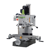
5.3 Adjust the height of Spindle
WARNING! Perform this adjustment must switch off
the power first.
1. Loosen the Spindle Height Lock(a).
2. Make sure the fence & table cleaning with milling tool.
3. Move the spindle up or down with the Spindle Height
Handwheel (b) until the desired position is obtained.
To raise = turn counter-clockwise
To lower = turn clockwise
Any height adjustment can be read directly from the scale(c).
4. Secure the Spindle Height Lock(a).
5.4 Fence adjustment
The fence is a two-piece adjusting system. Each fence is indepen-
dently adjustable to compensate for different cutting thicknesses
and special milling applications. To adjust the fence:
1. Loosen the fence lock handle(Startype Screw M8x25 a).
2. Turn the Spindle Latch Setting Knob(b) until the fence is set to
the desired position.
3. Tighten the fence lock handle.
CAUTION! Perform this adjustment, must wait the
spindle and milling tool standstill.
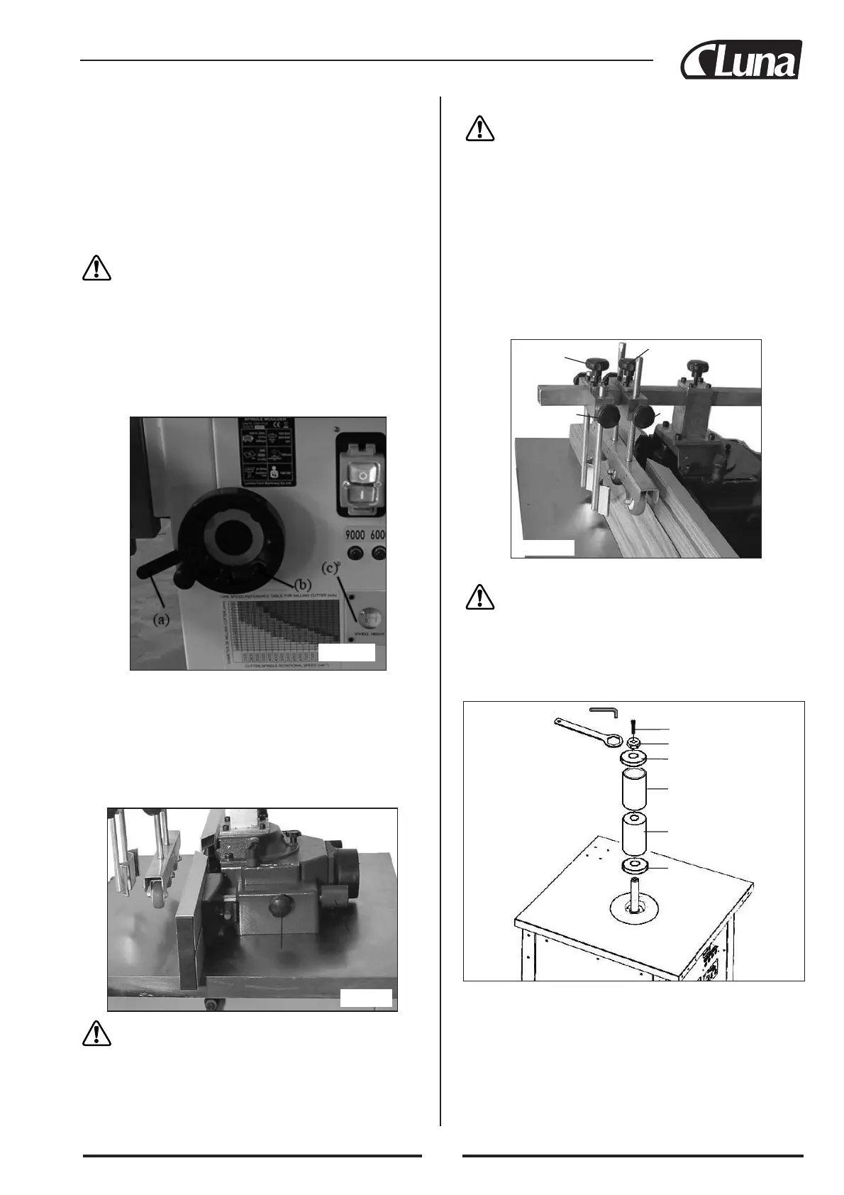
5.5 Adjust the Feed Roller
WARNING! Perform this adjustment must switch off
the power first.
1. Loosen the Startype Screw M8x25(a) and (b).
2. Move the Feed Roller above the workpiece.
3. Lock the Startype Screw M8x25(a), make feed roller on the cen-
ter line of workpiece.
4. Lock the Startype Screw M8x25(b), make secure the roller as
close as possible to workpiece.
5. Loosen the Startype Screw M8x25(c) and (d).
6. Move the Anti-kickback Plate near the workpiece.
7. Lock the Startype Screw M8x25(c), make the Plate is 5-10mm
above work table.
8. Lock the Startype Screw M8x25(d), make the plate is as close as
possible to the work piece.
5.6 Sanding
WARNING! Perform this operation must at 1800 R.P.M.
spindle speed.
1. Remove the Safer Guard and Feed Roller.
2. Adjust the spindle to Highest Position.
3. Insert the Sanding Drum(a) to Sanding Sleeve(b).
4. Place Support Disc(c) and Sanding Drum Ass’y onto spindle.
5. Secure the Lock Flange(d) with Allen Bolt M12x25(e).
6. DUST COLLECTION
This spindle moulder is operated indoors, it needs to be connected
to a dust collector of suitable capacity, i.e. having a minimum flow
rate of 20 mtr/sec. Connection should be made with a flexible suc-
tion hose of 100mm nominal diameter.
 Loading...