Line Voltage Wiring Details
• Use properly certified cable for all line
voltage/mains cables.
• Proper short-circuit and overload
protection must be provided at the
distribution panel.
• Install in accordance with all local and
national electrical codes.
• IEC PELV/NEC® Class 2 terminals may
be temporarily unplugged for ease of
contact closure and control wiring.
• Notice: Risk of damage to unit. Do not
connect line voltage/mains cable to IEC
PELV/NEC® Class 2 terminals.
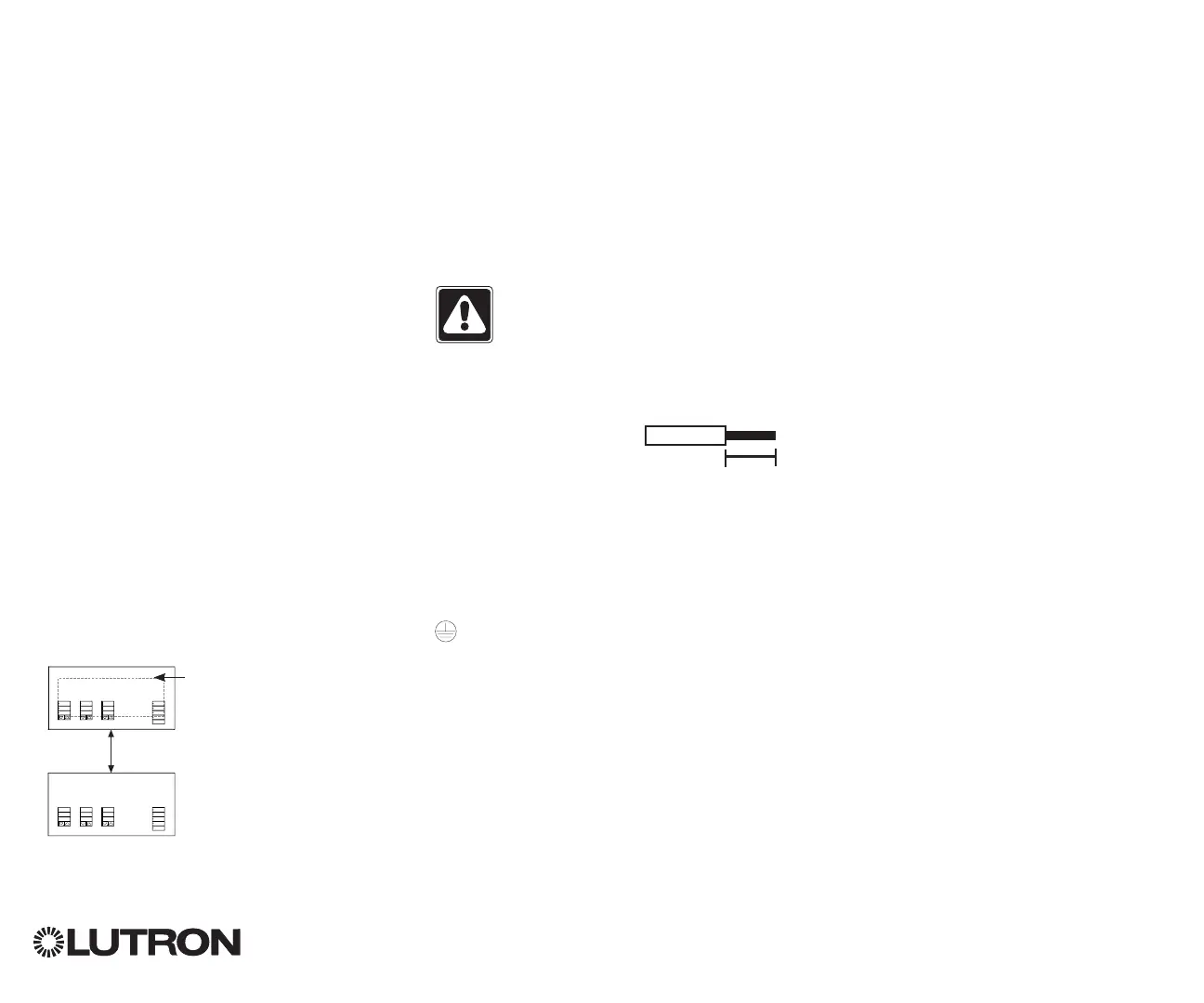
Step 1: Install wallbox. Mount a 3` in
(89 mm) deep 4-gang U.S. wallbox on a
dry, flat indoor surface that is accessible
and allows for system programming and
operation. Allow at least 4` in (110 mm)
clearance above and below the faceplate
to ensure proper heat dissipation. Allow
1 in (25 mm) for faceplate overhang on
all sides.
Note: 4-gang wallbox available from
Lutron; P/N 241400.
Step 2: Check wiring.
• Earth/ground terminal connection must
be made as shown in wiring diagrams
(see page 3).
• Follow all local and national electrical
codes when installing IEC PELV/NEC®
Class 2 wiring with line voltage/mains
wiring.
WARNING! Electric Shock hazard.
May result in Serious Injury or
Death. Always turn off circuit
breaker or remove main fuse from
power line before doing any work.
Step 3: Connect line voltage.
• Strip 9 in (8 mm) of
insulation off the line
voltage/mains cables in
the wallbox.
• Connect the line voltage/mains and
ground wires to the appropriate terminals
on the back of the timeclock.
L: Line / Hot
N: Neutral
: Ground
The recommended installation torque is
5.0 in∙lb (0.6 N∙m) for line voltage/mains
connections and 5.0 in∙lb (0.6 N∙m) for
the earth/ground connection.
Notice: Risk of damage to unit.
The QS Timeclock must be in stalled by
a qual i fied electrician in accordance with
all applica ble reg u la tions and building
codes. Im prop er wiring can result
in dam age to the timeclock or oth er
equipment.
QS Timeclock Installation and Operation Guide 4
Faceplate overhangs
wallbox on all sides;
allow 1 in (25 mm)
4` in
(110 mm)
9 in
(8 mm)
 Loading...


