Form # 147083 Issue 01/07
88
UNLOADING & ASSEMBLY
974 FLEX HEADER: WING FLOAT SET-UP AND PRE-DELIVERY CHECK
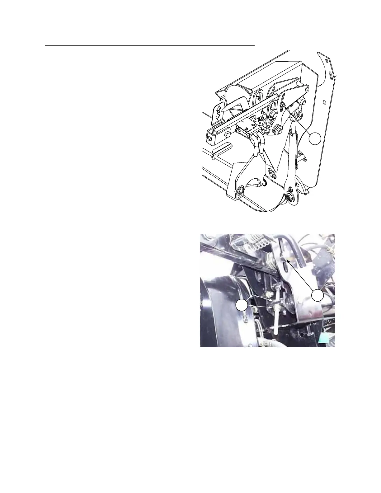
8. With adapter float spring lockout disengaged, wing
float lock pins engaged, and cutterbar
approximately 6” (150 mm) above ground, adjust
wing bell crank linkage to balance wings, as
follows:
NOTE: Fine tuning adjustment of wing bell crank
will be detailed in Step 9.
a) Adjust left wing:
• One of the two pins in the left wing float lock
will be tight and one will be loose.
• Loosen nut (N) inside bell crank.
• Adjust bell crank with nuts (P) until both wing
float lock pins are loose.
• Disengage pins in left wing float lock. Float for
right wing remains locked.
• To increase force on divider (making it harder
to pull up), adjust nuts (P) to move top link pin
(M) up. To decrease force on divider (making it
easier to pull up), adjust nuts (P) to move top
link pin (M) down.
• If nuts (P) are difficult to turn, fully lower feeder
house to reduce load on linkage. Return to 6”
(150 mm) cutterbar height when complete.
• Tighten nut (N).
b) Adjust right wing:
• Engage float lock pins in left wing.
Disengage pins in right wing float lock.
• Repeat bell crank adjustment above for right
wing.
c) Disengage pins in left wing float lock and
recheck float balance both sides. Readjust as
necessary.
Continued next page….
P
ADJUST BELL CRANK TO POSITION
TOP LINK PIN
M
LOOSEN NUT TO ALLOW
BELL CRANK ADJUSTMENT
N