UNLOADING AND ASSEMBLY
169558 34 Revision D
DETAILED PROGRAMMING INSTRUCTIONS
(Key ON / Engine Running or Not / Header Disengaged).
(Press PROGRAM and SELECT on CDM to enter Programming Mode).
NOTE: ENGINE MUST BE RUNNING TO CALIBRATE SENSORS.
L1Cxxx
||
WINDROWER SETUP?
L2Mxxx
||
N O /
ES C
B D I SPL
SETUP?
L1 C x x x
SELECT HE
DER T
PE?
L2 M x x x
||
DR
PER
L1 C x x x
SELECT HE
DER T
PE?
L2 M x x x
30
UGER
L1 C x x x
||
SELECT HE
DER T
PE?
L2 M x x x
40
UGER
L1 C x x x
TILT C
L INST
LLED?
L2 M x x x
N O /
ES
L1 C x x x
||
REEL FORE /
FT?
L2 M x x x
N O /
ES
L1 C x x x
||
KN I FE O
ERLO
DSPD?
L2 M x x x
||
1000 SPM
L1 C x x x
||
HE
DER INDEX MODE?
L2 M x x x
||
REEL & CON
E
OR
L2 M x x x
||
REEL ONL
L1 C x x x
||
RETURN TO CUT MODE?
L2 M x x x
||
HEIGHT & T I LT
L2 M x x x
||
HE IGHT ONL
L1 C x x x
||
HE
DER CUT WIDTH?
L2 M x x x
||
20.5 FEET
L1 C x x x
||
H
COND I T IONER?
L2 M x x x
||
N O /
ES
L1 C x x x
UGER HDR REEL SPD
L2 M x x x
||
RPM / MPH
L2 M x x x
||
RPM / KPH
L1 C x x x
SET T IRE S I
E?
L2 M x x x
||
18.4X26 TURF
L2 M x x x
||
18.4X26 B
R
L2 M x x x
23.1X26 TURF
L2 M x x x
600 - 65 R28
L2 M x x x
580 / 70R26 TURF
L1 C x x x
||
SET ENGINE I SC RPM?
L2 M x x x
||
N O /
ES SET CONTROL LOCKS?
L1 Cxxx
PRESS H
RD TO SET
L2 Mxxx
||
ISC RPM ON
L1 Cxxx
||
EXIT ENGINE ISC?
L2 Mxxx
||
NO /
ES
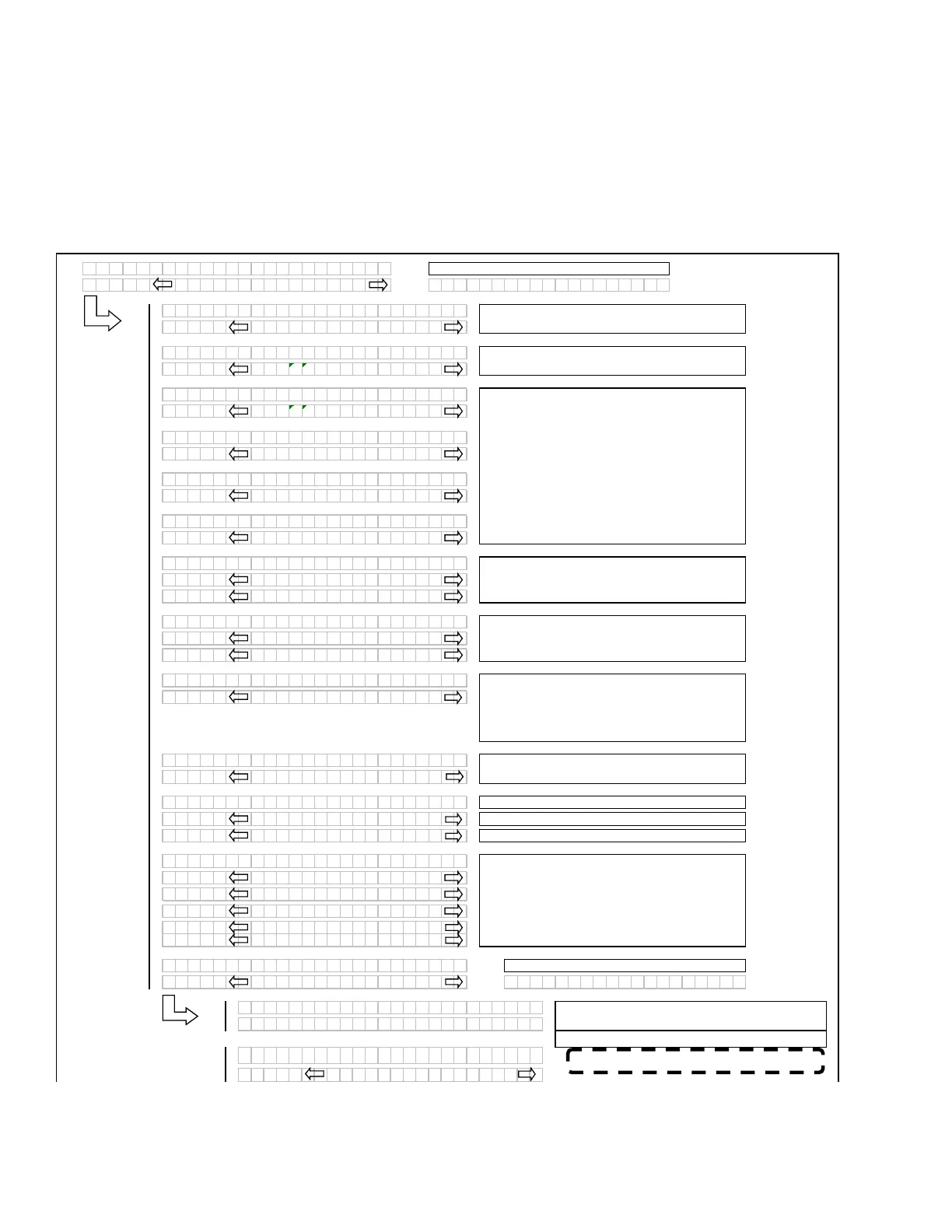
Programming Menu Flow Chart for Software version C107 and M102 (or higher)
If "NO" then
um
to:
If the REEL SPEED sensor is not “installed” (A30
Auger Header selected) in the WINDRWR SETUP
menu, the INDEX mode should be suppressed.
If the HEADER TILT sensor is not “installed” (no
expansion module installed), then the RTC mode
should default to HEIGHT only.
Selects the header type, the selected header will
be flashin
. The “factor
” default to be DRAPER.
If the A30 is selected then the reel speed should be
su
ressed as there is no reel s
eed sensor.
If a DRAPER or A40 is selected, the reel speed
should be enabled (with expansion module
installed
.
Knife Overload Speed should be suppressed
unless the ex
ansion module is installed.
AUGER HEADER ONL
Pressing “Select” goes to Exit Engine ISC
For IMPERIAL dis
la
.
If “NO” then
um
to:
If Choosing “YES” pressing “hazard”, choosing On
sets ISC to 2000 r
m
NOTE:
Set CUT WIDTH to represent actual
cutting width. This value should be less than actual
header width to accurately measure cut acres.
DRAPER HEADER ONLY. Default will be flashing.
Use “arrow” ke
s to select.
Use the “arrow” keys to set the header cut width.
NOTE:
When HYDRAULIC TILT CYLINDER is
physically installed, selecting “yes” will make this
cylinder operational. The tilt “reading” on the CDM
will only be active if an expansion module is
installed.
For METRIC dis
la
.
Pressing “SELECT” will go to the next line 1 (L1)
menu selection. The turn signal “arrow” keys are
used to change the values.
(continued next page)
NOTE: 2000 rpm SHOULD BE 2300 rpm.
 Loading...


