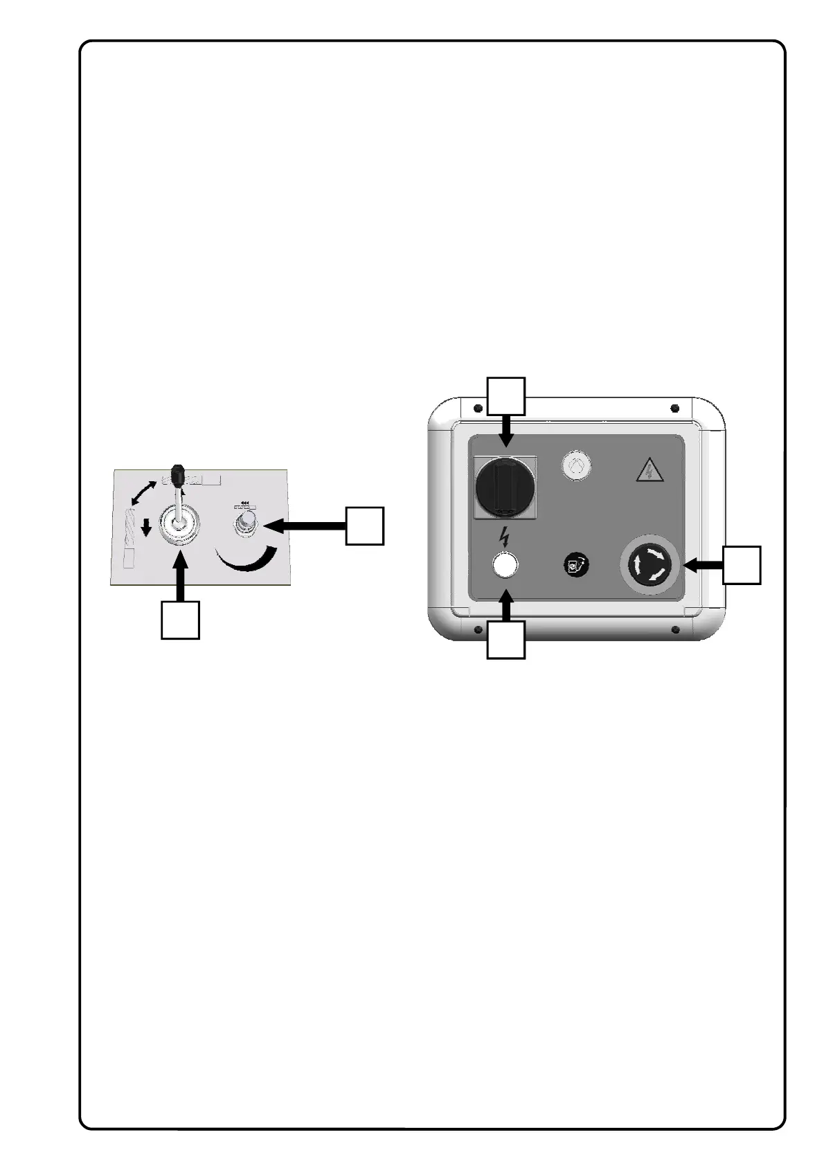
1 ) EMERGENCY ENGINE STOP BUTTON WITH RETAINER
Pressing this button all the electrical functions of the machine are cut off.
To resume the electrical functions, turn the mushroom button in the direction of the arrows.
2 ) MAIN SWITCH, ENGINE ENABLE BUTTON
Operating this ensures the presence of electrical energy; it enables the engine for switch on, hence for
turning the spindles during the work cycle.
3 ) ELECTRIC LINE AVAILABILITY WARNING LIGHT ON / OFF
The light on means that current is available; the light off means that electrical current is not available.
4 ) HEAD POSITIONING AT 0—90°
Pneumatic selector for operating the spindle head rotation mechanism by 0—90°.
5 ) FEED SPEED ADJUSTMENT
Controls the drill boring feed speed
6 ) PRESSURE REGULATOR
This is for regulating the compressed air operating pressure keeping it within the above-mentioned limits
( see paragraph 14.2 )
14.4 WORKING CYCLE
After setting the machine, follow the operations described below to start the working cycle:
1) Turn the main switch (2) to ON. The machine is ready to start the working cycle.
2) Operating the pneumatic pedal, the spindles turn and the head starts the working cycle, while the clamps
lock the piece in place.
3) If the pedal is released, the head returns to the rest position and the spindles stop.
4) The clamps release the piece when the head returns to the starting position.
Should it be necessary to interrupt the work cycle for any reason, press the emergency button (1).
14.3 MACHINE STARTING
The work station and control panel are on the machine electric panel. The operator places the pieces on the
work table after adjusting the stops.
14.5 CONTROL PANEL
2
1
3
5
4