EasyManua.ls Logo

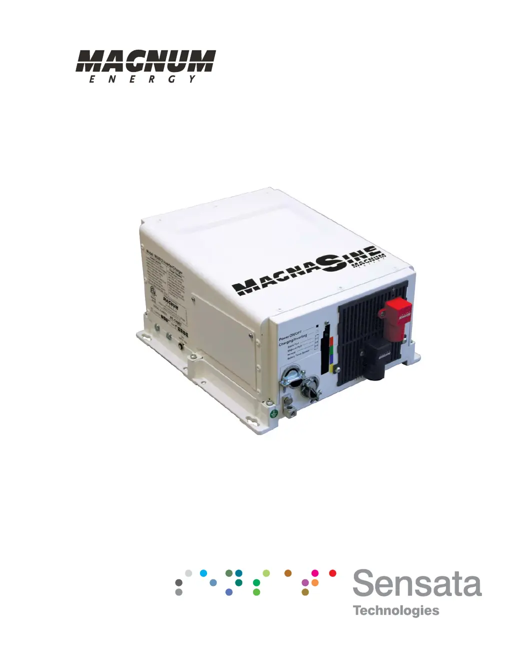
Magnum MS2000 - User Manual

Magnum MS2000
82 pages
Print Icon
To Next Page IconTo Next Page
Loading...
Pure Sine Wave Inverter/Charger
MS Series
Owners Manual

Table of Contents

Questions and Answers

  • G
    glaraJul 31, 2025
    Why is my Magnum Inverter charging at a low rate when connected to AC power?
    • T
      Timothy CordovaJul 31, 2025
      A low charging rate when connected to AC power can occur if the charge rate is set too low; adjust the charge rate or SHORE settings on the remote. It can also be caused by low AC voltage (less than 90 VAC); in this case, check the AC input wiring.
  • V
    Victoria CampbellAug 4, 2025
    Why is my Magnum Inverter charging at a low rate when using a generator?
    • N
      Nathan BrownAug 4, 2025
      A low charging rate when using a generator can be caused by the generator output being too low to power both the load and the charger. Try reducing the load or increasing the generator's RPMs. Also, check the SHORE settings if a remote is connected.
  • D
    denisejohnsonAug 12, 2025
    Why is my Magnum MS2000 charger not charging?
    • Y
      yparkAug 12, 2025
      The charger may not be charging due to several reasons. Check for loose or corroded battery cables and clean/tighten them. The batteries might be defective and need replacement. Verify that the charger settings are correct and ensure the unit is not in charger standby. Also, check that the AC input voltage is correct.
  • B
    Brent SmithAug 17, 2025
    What to do if my Magnum Inverter has low output or surge power and the Green LED is flashing?
    • D
      Daryl AtkinsAug 17, 2025
      This issue can arise from several causes: * Loose or corroded battery cables: Clean and tighten all cables. * Low batteries: Recharge or replace the batteries. * Loose AC output connections: Tighten the AC output connections. * Incorrect battery cable length or gauge: Verify the recommended cable lengths and gauges in the manual and replace cables if needed.
  • J
    John MarshallAug 21, 2025
    What does it mean if my Magnum MS2000 has no output power and the Green LED is flashing?
    • J
      James BurnsAug 21, 2025
      If your inverter has no output power and the green LED is flashing, it means the unit is in Search mode. This usually indicates that the load is too small for the Search mode circuit to detect. To resolve this, turn on a load greater than 5 watts to bring the inverter to full output power, or turn off Search mode using the remote.
  • J
    johncrawfordAug 26, 2025
    What causes the DC charge voltage to be higher or lower than expected while charging my Magnum MS2000 Inverter?
    • L
      Linda HicksAug 26, 2025
      If a Battery Temperature Sensor (BTS) is installed, the DC voltage will increase or decrease depending on the temperature around the BTS. This is normal.
  • N
    Nicole MarshallNov 7, 2025
    What to do if my Magnum Inverter has no output power and the Inverter LED is OFF?
    • E
      Emily RossNov 7, 2025
      First, ensure the inverter is switched ON. If it is, check the battery voltage at the inverter's terminals, as the battery voltage may be too low. Check fuses/circuit-breakers and cable connections. Your batteries may need to be charged; this fault condition will automatically clear when the battery voltage exceeds the LBCI voltage. Alternatively, the battery voltage may be too high; in this case, reduce or turn off any other charger to the inverter batteries to allow the voltage level to drop. It could also be due to an over-temperature condition; reduce the number of electrical loads to avoid a repeat shutdown, and check ventilation around the inverter. It may also be caused by an AC overload condition; reduce the AC loads or remove all AC output wiring and restart the inverter. Finally,...

Summary

Safety Information

IMPORTANT SAFETY INSTRUCTIONS

Key instructions for safe installation and operation of the MS Series inverter/charger.

Safety Precautions

General safety guidelines for electrical work, product handling, and installation.

Safety Information - Battery Safety

Battery Safety

Precautions and guidelines for safely handling and working with batteries.

Introduction - Inverter Operation

1.1 How an Inverter;Charger Works

Explanation of the two operating modes: Inverter Mode and Standby Mode.

Introduction - Component Identification

7 DC Equipment Ground Terminal

Connection point for grounding the inverter's chassis to the DC grounding system.

8 AC Entry;Exit Connections

Access points for AC wiring with strain relief for input and output.

Introduction - Unit Features

15 AC Access Cover

Cover providing access to the internal AC wiring terminal block.

16 AC Input Circuit Breaker (CB3)

Protects internal charger wiring and pass-thru relay in Standby mode.

17 AC Output Circuit Breakers (CB1 & CB2)

Branch-rated breakers for connecting AC loads directly to inverter output.

Installation

2.0 Installation

General guidelines and safety precautions for installing the MS Series inverter/charger.

2.1 Pre-Installation

Steps and checks to perform before beginning the inverter installation.

Installation - Pre-Installation

Installation - Locating the Inverter

2.1.3 Locating the Inverter

Requirements for choosing a suitable installation location for the inverter.

Ventilation

Requirements for airflow and clearance around the inverter for cooling.

Installation - Mounting

2.2 Mounting the Inverter

Instructions and guidelines for physically mounting the inverter.

Installation - Wiring Requirements

2.3 Wiring the Inverter - General Requirements

General requirements and recommendations for all inverter wiring.

2.3.2 Wiring Requirements

Guidelines for conductor protection, insulation, and wire routing.

Installation - DC Wiring

2.4 DC Wiring

Guidance on DC wire sizing, disconnect/overcurrent protection, and connections.

2.4.1 DC Wire Sizing

Importance of correct DC wire sizing for efficiency, safety, and performance.

Installation - DC Wiring Details

2.4.2 DC Overcurrent Protection

Requirements for DC overcurrent protection and disconnect switches for safety.

2.4.3 DC Cable Connections

Proper procedures for making DC cable connections to terminals.

Installation - Battery Bank Wiring

2.4.4 Wiring the Battery Bank

Guidelines for connecting the inverter to the battery bank.

Installation - Temperature Sensor

2.4.5 Battery Temperature Sensor Installation and Wiring

Steps for installing and wiring the Battery Temperature Sensor (BTS).

Installation - Inverter to Battery Connection

2.4.6 Wiring the Inverter to the Battery Bank

Detailed steps for connecting the inverter to the battery bank.

DC Ground Wire

Instructions for routing and connecting the DC equipment ground wire.

DC Positive Wire

Steps for mounting the breaker/fuse, routing, and connecting the DC positive wire.

Installation - AC Wiring

2.5 AC Wiring

Information on AC wiring, wire size, and overcurrent protection.

2.5.1 Pre-AC Wiring Requirements

Safety precautions and requirements before making AC wiring connections.

2.5.2 AC Wire Size and Overcurrent Protection

Sizing AC wiring and providing overcurrent protection per safety codes.

Installation - AC Wiring Connections

2.5.3 Recommended GFCI (Ground Fault Circuit Interruption) Outlets

Tested GFCI outlets compatible with the inverter's AC output.

2.5.4 AC Terminal Connections (MS2012, MS2812, MS2024, MS4024, & MS4048)

Details on connecting AC input/output wiring to the terminal block.

Installation - AC Conductor Wiring

2.5.5 AC Conductor Wiring (MS2012, MS2812, MS2024, MS4024, & MS4048)

Step-by-step guide for connecting AC wiring to these inverter models.

Wiring the Inverter AC Input

Steps for connecting the AC input wiring from the main panel.

Installation - AC Wiring Details

Wiring the Inverter AC Output

Steps for connecting the AC output wiring to the sub-panel or outlets.

Wiring the Inverter AC Ground

Connecting the AC ground wire from the main and sub-panels.

Installation - MS2000 Model Wiring

2.5.7 AC Conductor Wiring (MS2000 models)

Guide for connecting AC wiring for MS2000 models.

2.5.8 AC Wiring Configuration (MS2000 models)

Table detailing AC input/output wiring configurations for MS2000 models.

Installation - Grounding Inverters

Installation - Grounding Methods

Installation - Grounding Methods Details

Installation - Bonding and Grounding

Installation - Marine Grounding

Installation - Neutral Ground Bonding

Installation - Grounding Disconnection

Installation - Notification and Inspection

Installation - Functional Testing

CAUTION

Caution about using a multimeter for DC voltage verification.

Operation

Operation - Inverter Mode Details

Operation - Standby Mode

Operation - Battery Charging

Operation - Charging Stages

Operation - Charging and Transfer

Operation - Battery Temperature Sensor

Operation - Protection Features

Operation - Protection Details

Operation - Fault Conditions

Operation - Startup Indicators

Operation - Default Settings

Operation - Fans and Remote Control

Maintenance and Troubleshooting

Maintenance and Troubleshooting - Storage

Maintenance and Troubleshooting - Troubleshooting

Maintenance and Troubleshooting - Resetting

Maintenance and Troubleshooting - Power Reset

Appendix B - Battery Information

WARNING

Warning about high currents from short-circuited batteries.

Appendix B - Battery Details

Appendix B - Battery Sizing

Appendix B - Sizing Calculations

Appendix B - Battery Wiring

Appendix B - Wiring Configurations

Magnum MS2000 Specifications

General IconGeneral
Continuous Output Power2000W
Input Voltage12 VDC
Output Voltage120 VAC
Output Frequency60 Hz
Efficiency90%

Related product manuals