MP1900X Series Router Installation Manual Router Introduction
copyright2019 Maipu, all rights reserved
1-3
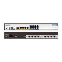
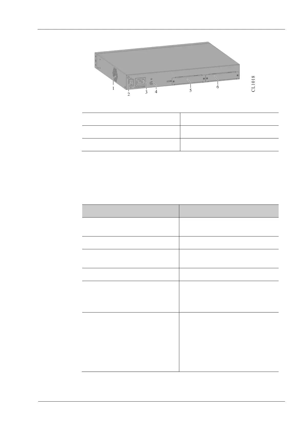
Figure 1-4 The rear appearance diagram of MP1900X-22-AC
1. Fan outlet 2. Power switch
3. Power socket 4. Grounding screw
5.S1 slot of RM2B interface sub card 6.S2 slot of RM2B interface sub card
1.3 Panel Specifications of MP1900X Series Router
The interface description is as shown in the following table:
Table 1-1 Interfaces on the front panel of MP1900X series router
Interface Name Description
Reset function button Press it for 3s, and the system restarts
and restores the factory setting
USB One USB interface, USB2.0 standard
CONSOLE Console port, one RJ45 interface, asyn
series port, default baud rate: 9600bps
Micro USB Console port, one Micro USB interface
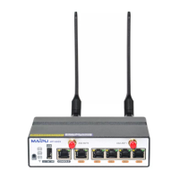
GE0~GE4 port WAN port
MP1900X-12-AC: 1 GEF
MP1900X-22-AC: 1 GEF +4 GET
GE0/0~ GE0/7 port LAN port/ WAN port
Eight RJ45 interface,
10M/100M/1000M Ethernet port,
support auto crossing of data receiving
and sending
MP1900X-12-AC: eight ports
MP1900X-22-AC: eight ports
The meanings of the panel indicators are as follows:
 Loading...