8 ENGLISH
Displayed
Number
Speed Torque Applicable
operation
1 Low High -
ing operation
2 High Low Light loading
operation
operation.
and restart the operation.
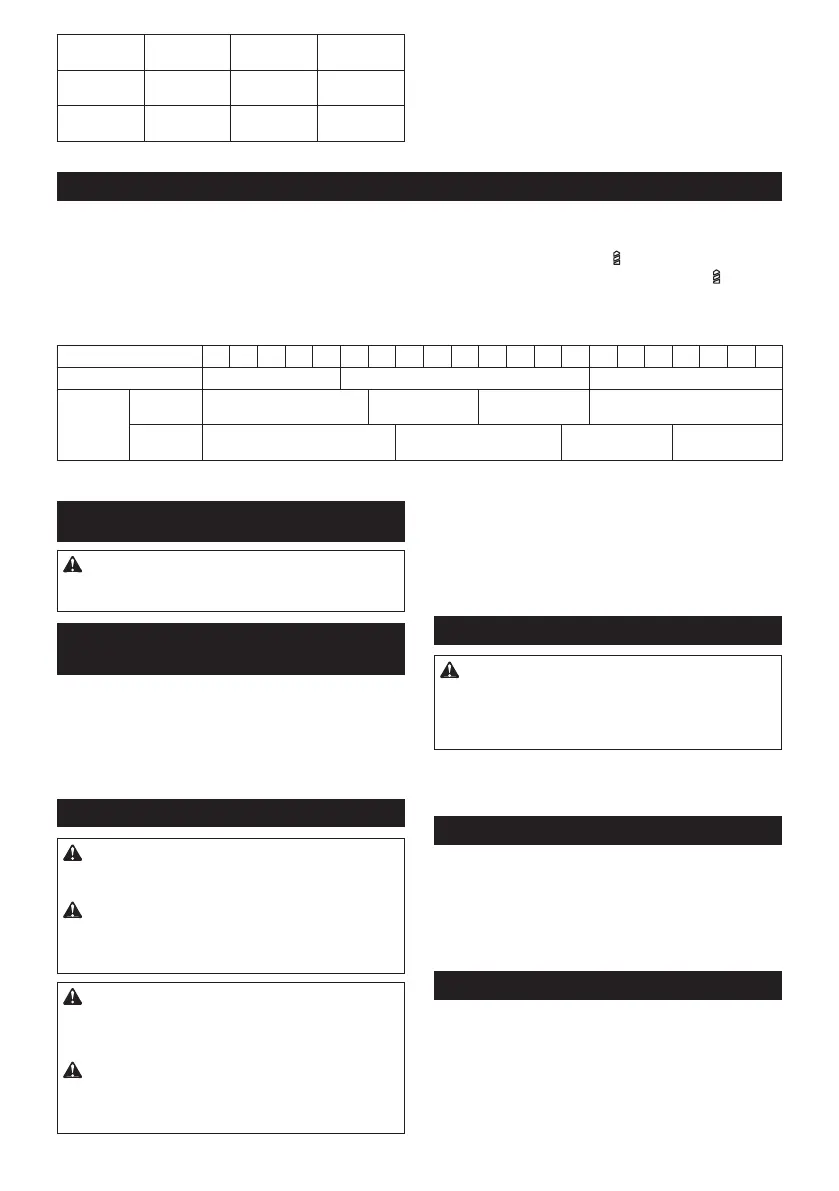
Adjusting the fastening torque
Fig.7: 1.2. Graduation 3.
marking.
marking.
torque level is required for a particular application.
Graduation 1 2 3 4 5 6 7 8 9 10 11 12 13 14 15 16 17 18 19 20 21
Machine screw M5 M6
Wood
screw
Soft wood
(e.g. pine)
– ø3.5 x 22 –
Hard wood
(e.g. lauan)
– ø3.5 x 22 –
ASSEMBLY
CAUTION: Always be sure that the tool is
before carrying out any work on the tool.
Installing or removing driver bit/
drill bit
Fig.8: 1. Sleeve 2. Close 3. Open
Turn the sleeve counterclockwise to open the chuck
as it will go. Turn the sleeve clockwise to tighten the
counterclockwise.
Installing hook
WARNING: Use the hanging/mounting parts
for their intended purposes only, e.g., hanging the
tool on a tool belt between jobs or work intervals.
WARNING: Be careful not to overload the
hook as too much force or irregular overburden
may cause damages to the tool resulting in per-
sonal injury.
CAUTION: When installing the hook, always
If not, the hook
CAUTION: Make sure to hang the tool
securely before releasing your hold.
Fig.9: 1. Groove 2. Hook 3. Screw
the hook, insert it into a groove in the tool housing on
either side and then secure it with a screw. To remove,
loosen the screw and then take it out.
Using hole
WARNING: Never use the hanging hole for
unintended purpose, for instance, tethering the
tool at high location.
-
Fig.10: 1. Hanging hole
tool on a wall using a hanging cord or similar strings.
Installing driver bit holder
Optional accessory
Fig.11: 1.2.
on either right or left side and secure it with a screw.
Installing side grip (auxiliary handle)
Optional accessory
Fig.12: 1.2.3. Recess 4. Grip
Insert the side grip so that the protrusions on the arm
turning clockwise.
either right or left side of the tool.

 Loading...