13 ENGLISH
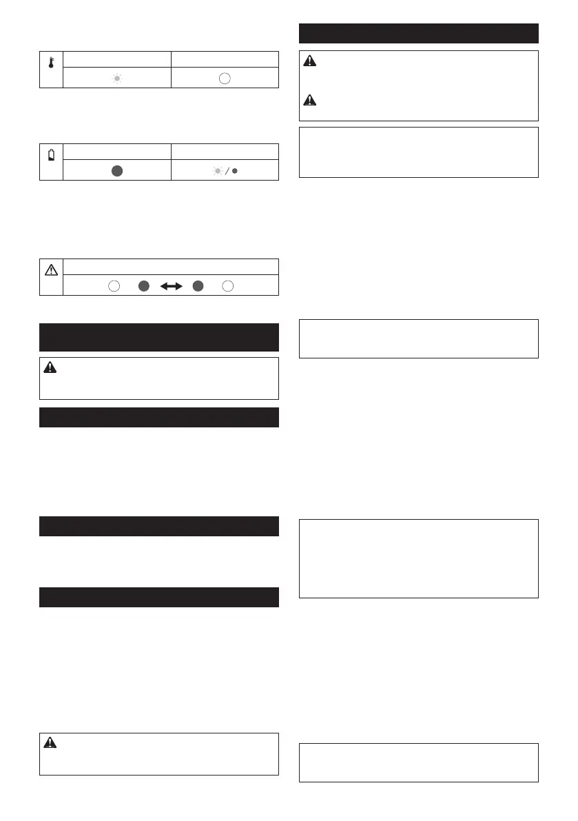
• Greenlampblinks:thetoolisoverheated.Letthe
toolcooldownbeforeturningthetoolonagain.
Green Red
• Greenlamplightsupandredlampblinksorlights
up:batteryisloworalmostat.Chargethebatter-
ies.Wheneitherofthebatterybecomeslow,the
redlampblinksevenoneofthebatteriesisfull.
Green Red
•
Greenlampandredlampblinkalternately:thetool
detectsbreakingofwire.Checktheconnectioncordfor
looseconnectionwiththeswitchboxandtheshears.If
thelampsstillblinkalternately,stopusingthetoolimmedi-
ately,disconnecttheconnectioncord,removethebattery,
and ask your local authorized service center for repair.
Lampsblinkalternately
ASSEMBLY
CAUTION: Always be sure that the tool is
switched off and the battery cartridge is removed
before carrying out any work on the tool.
Installing the battery holder into the backpack
►Fig.9: 1. Clamp 2. Battery holder 3. Strap
1. Passtheswitchboxthroughtheopening(either
rightorleft)ofthebackpack.
2.
Passtheclampthroughthesquareholeofthebattery
holder,andsecurethebatteryholderwiththestrap.Make
surethatthebatteryholdersitsinthebackpackrmly.
Installing the holster
►Fig.10: 1. Holster 2. Strap
Passthebeltofthelowerbucklethroughtheopeningof
the holster.
Adjusting the harness
Adjusttheharnessasfollows:
1.
Closeandlockthelowerbuckle,andadjustitsbeltlength.
►Fig.11: 1.Lowerbuckle
2. Adjusttheshoulderstraplength.
►Fig.12
3. Adjustthepositionoftheupperbuckle.Closeand
locktheupperbuckleandadjustitsbeltlength.
►Fig.13: 1.Upperbuckle
CAUTION: In case of emergency, quickly
open the lower buckle and upper buckle, loosen
shoulder straps, and set down the backpack.
Installing the connection cord
CAUTION: Always make sure that the switch
box's I/O switch is on the "O" side before attach-
ing the connection cord.
CAUTION: Do not operate the tool if the con-
nection cord is damaged.
NOTICE:Donotabusetheconnectioncord.Donot
carrythetoolbypullingtheconnectioncord.Keepthe
connection cord away from heat, oil, or sharp edges.
Otherwisetheconnectioncordmaybedamaged.
Attachtheconnectioncordwiththeswitchboxandthe
shears as follows:
1. First, align the triangular marks of the male plug
of the connection cord with the triangular mark of the
femaleconnectoroftheswitchbox.Pushintheplugof
theconnectioncordtotheconnectoroftheswitchbox.
Then, align the marking on the coupling with the trian-
glar marks, and push in and turn the coupling to tighten.
►Fig.14: 1. Triangular mark 2. Connection cord
3.Switchbox4. Marking on coupling
5. Coupling
NOTICE: Turn the coupling and align the marking
onthecouplingwiththetriangularmarksrstwhen
disconnectingtheconnectioncable.
2.
Hangtheswitchboxonthewaistbeltorupperbelt.
►Fig.15
3.
Push the connection cord into the loop of the cord holder.
►Fig.16
Hangthecordholderoneithertheupperbeltorthe
waistbeltonwhichtheswitchboxisnothung.
The cord holder prevents the connection cord from dan-
glingaroundyourbody,andalsothecordholdercan
preventtheconnectioncordfrombeingcutbymistake.
►Fig.17
►Fig.18
NOTICE: Do not hang anything other than the
connection code on the cord holder. Otherwise the
codeholdermaybebroken.
NOTICE: Do not force the cord holder opening.
Otherwiseitmayresultindeformationorbreakageof
the code holder.
4. Putthearmbandonyourarm.Andslipthecon-
nectioncordthroughthearmband.
►Fig.19: 1.Armband
5. First, align the triangular marks of the female
socket of the connection cord with the triangular mark
of the male connector of the shears. Push in the socket
of the connection cord to the connector of the shears.
Then, align the marking on the coupling with the trian-
glar marks, and push in and turn the coupling to tighten.
►Fig.20:
1. Triangular mark 2. Connection cord
3. Shears 4. Marking on coupling 5. Coupling
NOTICE: Turn the coupling and align the marking
onthecouplingwiththetriangularmarksrstwhen
disconnectingtheconnectioncable.

 Loading...