1
2
Removing and installing valve guides
90
D For removing and installing cylinder head,
see page 79
D For removing and installing valves,
see page 87
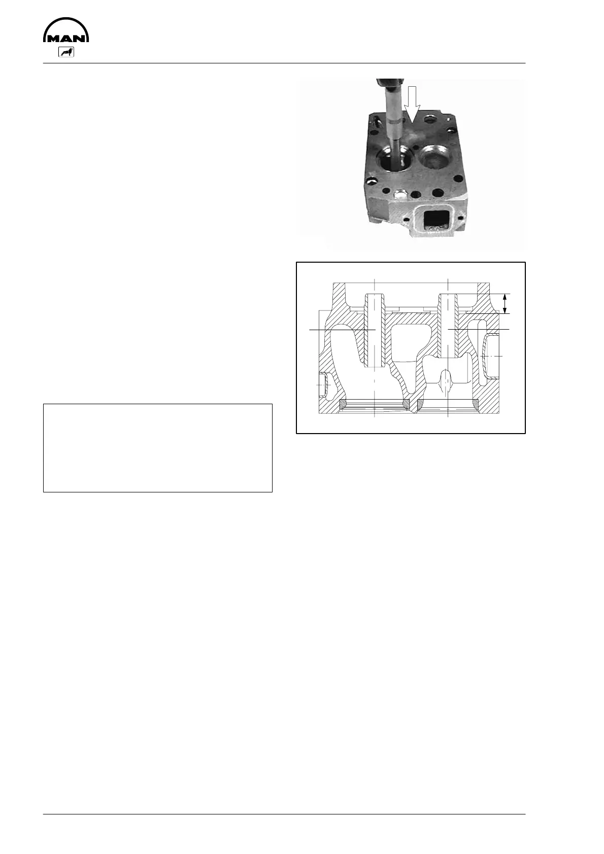
Fig. 1
Press valve guide out of the combustion chamber
side using pressing mandrel (special tool, see
page 129, item 20).
Oil new valve guide and drive/press it into the cyl-
inder head using pressing mandrel and spacer
sleeve (special tool).
Fig. 2
The valve guides vary only in length.
1 Inlet = long guide
2 Exhaust = short guide
3 Press-in depth (see publication ”Engineering S
Data S Setting values”).
The correct press-in depth is obtained by using the
spacer sleeve.
Afterwards ream valve guide to specified
dimension.
Note:
When the valve guides have been changed,
the valve seats too must be reworked (see
technical data and manufacturers’ instruc-
tions for valve seat lathes found in individual
workshops).
3533
3
2
1
2818
 Loading...