4
5
6
7
Reworking valve seat
94
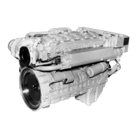
Fig. 4
Release Jaccard lever, place magnetic flange flush
on the clamping plate and set the height so that
the tool does not contact the valve seat.
Set toggle switch to position 1.
Tighten the Jaccard lever.
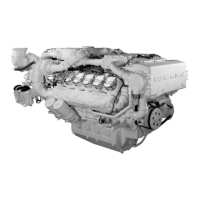
Fig. 5
Machine the valve seat by turning the driving crank
evenly in clockwise direction and simultaneously
operating the feed nut.
Caution:
During the machining process turn the driv-
ing crank vigorously and evenly but under no
circumstances against the direction of turn-
ing, as otherwise the carbide cutting edge
may break.
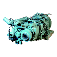
Fig. 6
Once the valve seat has been expertly machined,
reduce the working pressure of the tool by 2-3 rev-
olutions without feed motion.
During these revolutions turn the feed nut 2-3 rev-
olutions back.
Press toggle switch briefly to position 2 to lift the
magnetic field.
Now move the whole Mira unit out upwards and
insert it into the next valve guide, repeating the
centering operation.
Use the same tool settings for all intake and all
exhaust valve seats (see below).
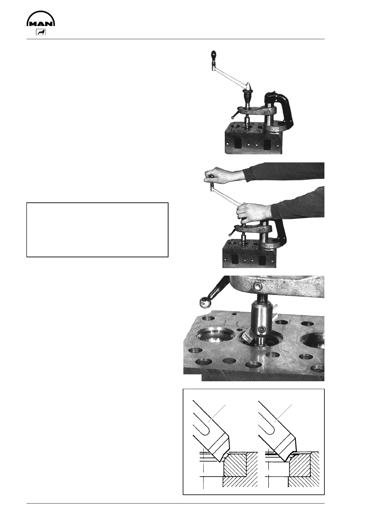
Fig. 7
Observe specified seat angle.
1 Exhaust, total angle: 90_, tool setting: 45_
2 Inlet, total angle: 120_, tool setting: 30_
Repeat the chip-removing machining process until
the valve seat is clean and free of pores.
3361
3362
3363
2819
21
 Loading...