82
IT
EN NL
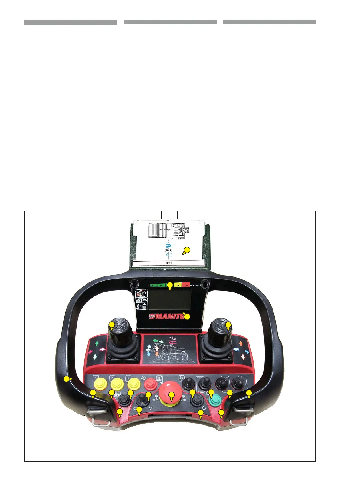
PULSANTIERA
1 - Display funzioni macchina e stato
del carico
(Vedi immagine 43, punto 1)
2 - Comandi macchina e accessorio:
• manipolatori per il controllo
proporzionale,
(Vedi immagine 43, punto 2)
• selettori, pulsanti e interruttori che
consentono l’attivazione di funzioni
digitali ON/OFF
(Vedi immagine 43, punto 2)
3 - Pulsante a fungo per la funzione di
arresto d’emergenza (STOP)
(Vedi immagine 43, punto 3)
4 - Interruttore avviamento motore
(Vedi immagine 43, punto 4)
5 - Attivazione pulsantiera
(Vedi immagine 43, punto 5)
6 - Pulsante elettropompa d’emergenza
per il salvataggio del cestello porta
persone
(Vedi immagine 43, punto 6)
7 - Acceleratore/decelatore giri motore
(Vedi immagine 43, punto 7)
8 - Interruttore velocità movimenti idraulici
con accessorio gru
(Vedi immagine 43, punto 8)
9 - Presa per locomando (non utilizzata)
(Vedi immagine 43, punto 9)
10 - Schede movimenti accessori
(Vedi immagine 43, punto 10)
11 - Scorrimento pagine display
(Vedi immagine 43, punto 11)
1
10
2
2
2
2
7
4
2
2
2
2
3
8
5
11
6
1
9
43
KNOPPENBORD
1 - Display machinefuncties en staat van de lading
(Zie afbeelding 43, punt 1)
2 - Bedieningen machine en werktuig:
• stuurknuppels voor proportionele besturing (Zie
afbeelding 43, punt 2)
• keuzeschakelaars, knoppen en schakelaars
waarmee digitale ON/OFF functies geactiveerd
kunnen worden (Zie afbeelding 43, punt 2)
3 - Paddelstoelvormige knop voor de noodstop
(STOP)
(Zie afbeelding 43, punt 3)
4 - Motor startschakelaar.
(Zie afbeelding 43, punt 4)
5 - Activering knoppenbord
(Zie afbeelding 43, punt 5)
6 - Knop elektrische noodpomp voor de
reddingsprocedure van het personenplatform
(Zie afbeelding 43, punt 6)
7 - Knop voor versnellen/vertragen motortoerental
(Zie afbeelding 43, punt 7)
8 - Schakelaar voor snelheid hydraulische
bewegingen met kraanwerktuig
(Zie afbeelding 43, punt 8)
9 - Contactpunt voor draadbediening (niet
gebruikt)
(Zie afbeelding 43, punt 9)
10 - Kaarten werktuigbewegingen
(Zie afbeelding 43, punt 10)
11 - Displaypagina’s doorlopen
(Zie afbeelding 43, punt 11)
PUSHBUTTON PANEL
1 - Machine functions and load status
display
(See image 43, point 1)
2 - Vehicle and attachment controls:
• manipulators for the proportional control
(See image 43, point 2)
• selectors, pusbuttons and switches which
allow activation of the digital functions ON/
OFF
(See image 43, point 2)
3 - Mushroom-shaped pushbutton for
emergency stop function (STOP)
(See image 43, point 3)
4 - Engine start-up switch
(See image 43, point 4)
5 - Pushbutton panel activation
(See image 43, point 5)
6 - Emergency motor pump button for
platform rescue
(See image 43, point 6)
7 - Engine rpm accelerator/decelator
(See image 43, point 7)
8 - Hydraulic movements speed switch with
crane attachment
(See image 43, point 8)
9 - Socket for wired control (not used)
(See image 43, point 9)
10 - Attachments movements charts
(See image 43, point 10)
11 - Display pages scrolling
(See image 43, point 11)
 Loading...