2-10
Description - STACKY 2012.12
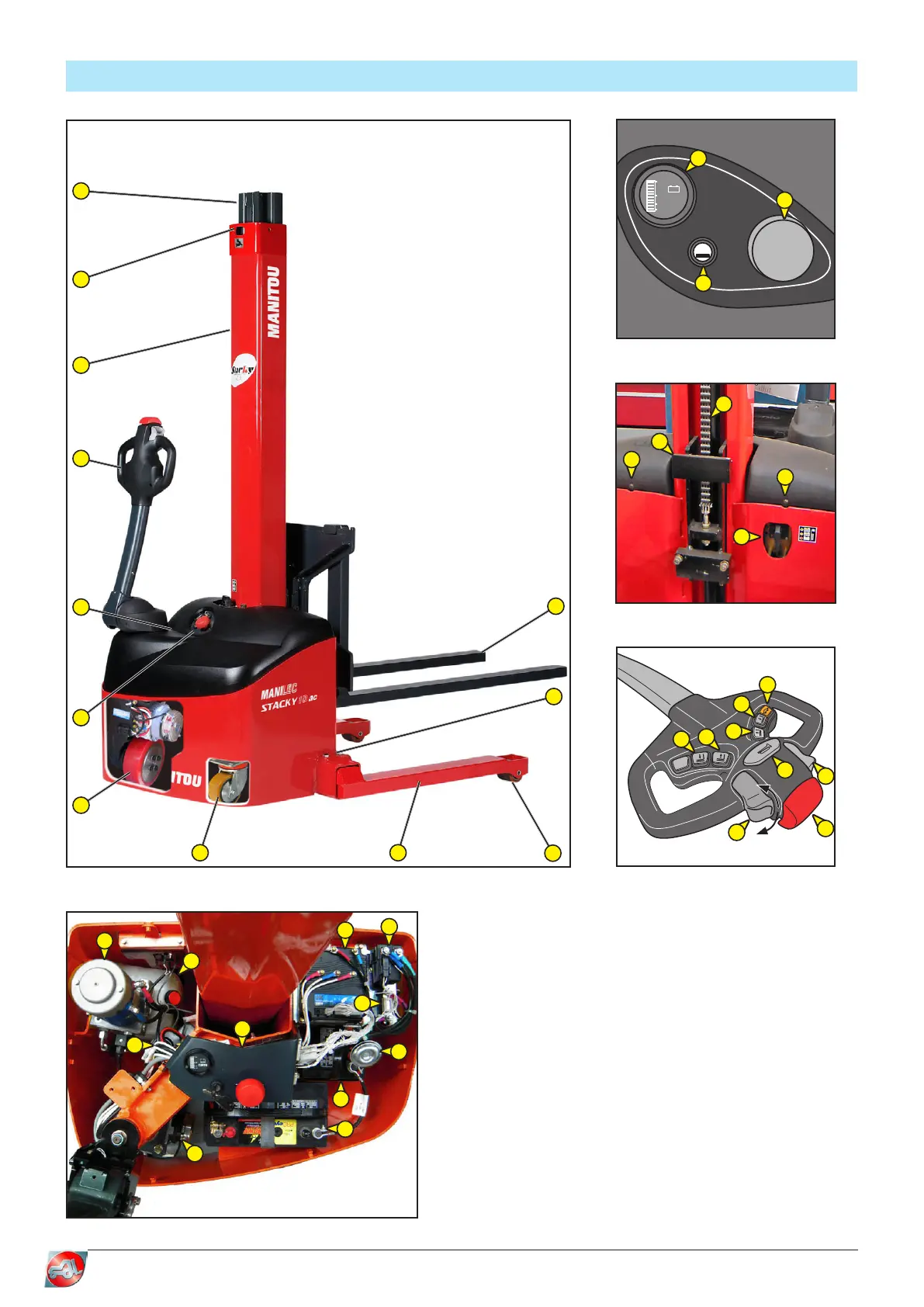
TECHNICAL DESCRIPTION
Key
1 - Moving frame
2 - Slinging point
3 - Chassis
4 - Tiller arm
5 - Cover fastening screw
6 - Dashboard
7 - Drive unit
8 - Stabiliser wheel
9 - Support leg
10 - Roller
11 - Support leg adjustment
screw (LE model only)
12 - Fork or tool
13 - Charge indicator
14 - Emergency stop button
15 - Key switch
16 - Carriage
17 - Lifting chain
18 - Charging lead
19 - Down button
20 - Up button
21 - Tortoise button
22 - Horn button
23 - Buttery control switch
24 - Anti-crushing safety device
25 - Hydraulic unit
26 - Oil tank
27 - Electronic speed controller
28 - Switch
29 - Battery charger
30 - Fuses
31 - Horn
32 - Batteries
VOLTS
28
22
19
16
-
+
13
14
15
17
16
5
5
18
23
24
22
19
20
21
23
19
20
4
5
1
2
3
6
7
8 9
12
10
11
29
25
27
31
32
32
7
26
5
28
30