2-11
2012.12 Description - STACKY
DESCRIPTION
1 - MOBILE FRAME (duplex model only)
The lifting mast comprises a xed part, the chassis, and a moving part, the moving frame. The moving part receives the carriage
onto which the tool is attached. A hydraulic cylinder slides the moving frame within the chassis. A drive belt/chain transmits the
translation movement of the cylinder to the moving frame and the carriage. According to the stacker model, the lifting stroke
is between 818 and 2740 mm.
2 - SLING ATTACHMENT POINT
This sling attachment point provided on the chassis is used for handling the stacker by (overhead) crane.
3 - CHASSIS
The chassis receives the carriage (simplex model) or the moving frame (duplex model)
that slides within it.
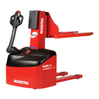
4 - TILLER ARM
The tiller arm controls and steers the stacker. It has a driving zone (2) (g. 4). In zones
(1) and (3) (g. 4) the wheels are mechanically locked. When it is within the driving zone,
the tiller is used to move the stacker forwards or backwards by pushing the buttery
control switches (23) up or down. When moving, the stacker must be behind the
operator. The stacker thus follows the direction of the operator.
5 - COVER FASTENING SCREW
The cover is fastened to the chassis by means of four screws. Two of these screws
are located on the fork side, the other two at the base of the tiller arm.
6 - DASHBOARD
The dashboard includes a charge indicator (13), an emergency stop button (14),
and the key switch (15).
7 - DRIVE UNIT
This item comprises in particular an electric motor, a brake and the drive wheel. It is connected to the tiller arm that steers
the machine.
8 - STABILISER WHEEL
This caster wheel forms the fourth bearing point of the stacker.
9 - SUPPORT LEG
On the STACKY 10 FR and STACKY 14 stackers, the support legs are xed. On the LE model, the spacing of the two legs is variable
between 900 and 1280mm.
10 - ROLLER
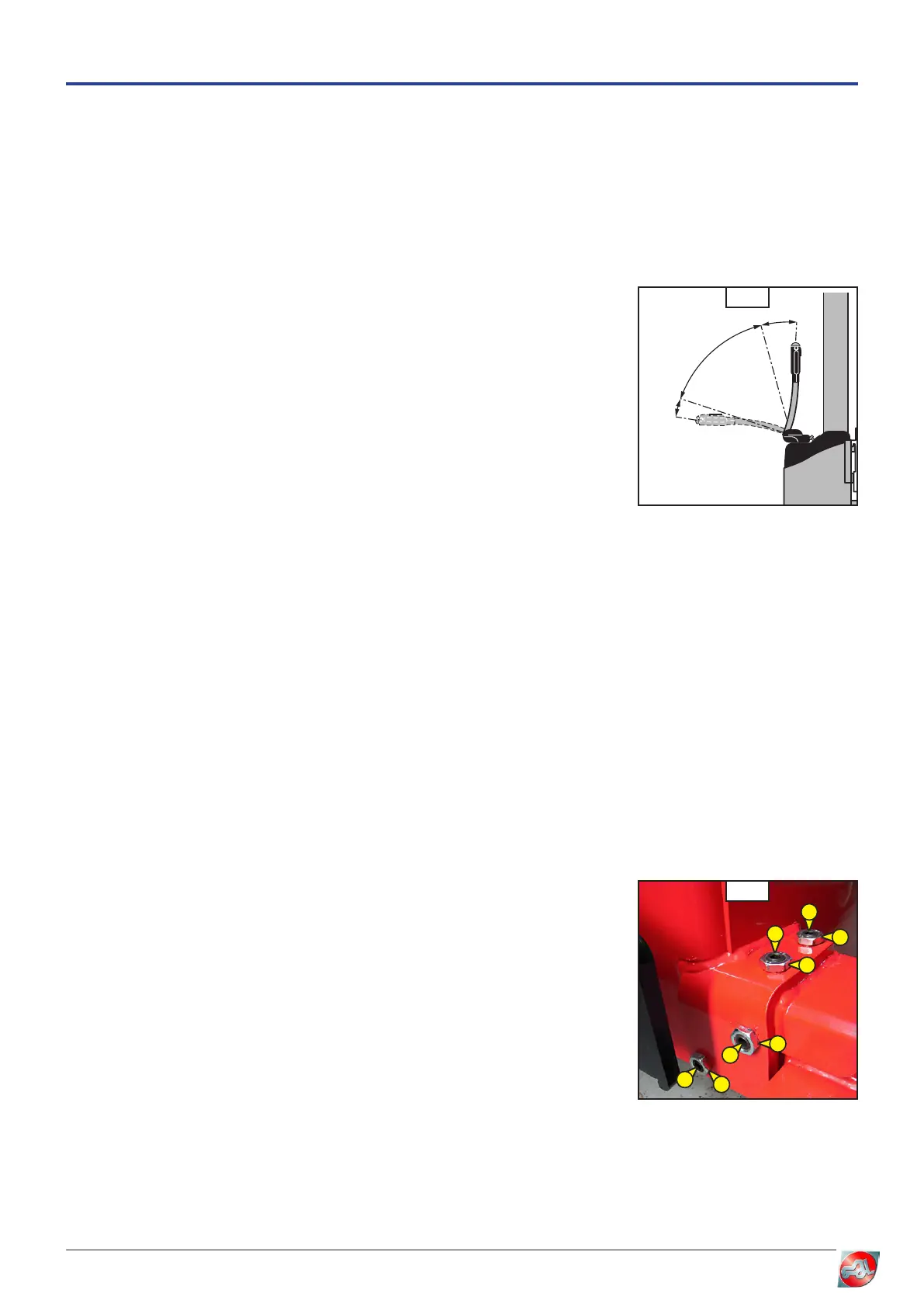
11 - SUPPORT LEG ADJUSTMENT SCREWS (LE model only)
These four screw (1) and (2) (g. 11) are used to alter the support leg spacing on STACKY LE stackers.
To adjust the support legs :
- check that the stacker is on level ground,
- sling the stacker,
- lift the stacker with an overhead crane,
- loosen lock nuts (1) (g. 11),
- loosen screws (2) and (3) (g. 11),
- adjust the support leg spacing, keeping them symmetrical,
- bring the screws into contact without tightening,
- set down the stacker,
- tighten screws (2) (g. 11),
- tighten screws (3) (g. 11),
- tighten lock nuts (1) (g. 11).
12 - FORK OR TOOL (except STACKY 14)
The tool mounted on the stacker must be the appropriate tool for the task to be performed.
Only tools approved by MANITOU can be used on the stacker.
The tools are attached to the carriage by means of a hook and two M10 screws. Some tools are provided with a lifting ring
for ease of handling (jib, narrow-aisle fork).
3
2
1
4
11
1
1
1
1
2
2
3
3